RUIDENG TC64
The RUIDENG TC64 is a very low cost (<$15) USB-C inline power meter. It’s small with a very nice colour OLED screen. It tries to automatically detect if the USB lines are running in a few modes (QC, DCP etc). This unit is very handy for measuring the power consumption of USB-C devices, and it is moderately accurate (Good enough anyway for the price). It’s over on BangGood over here
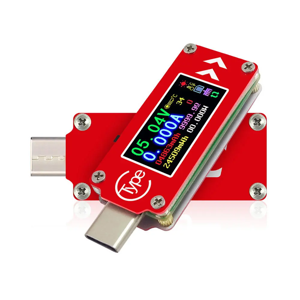
Bang Goods picture
The usual review
Honestly, I only bought the unit as a lazy way to measure the current being used by the TS-80 from Miniware while setting up my new firmware. In terms of this use, it works quite well, with milliamp resolution that responds fairly quickly. Around a one-hertz update rate, but doesn’t bounce or overly filter the data so fairly good.
Internally its a small 8051 based Nuvoton N76E003AT20 MCU ($0.3 each), which appears to connect to the OLED and use its internal ADC to measure the supply voltage via a voltage divider. A small op-amp amplifies the current shunt and then this is measured with is op-amp.
The only issue with this unit at all is that it measures current the wrong way around. When I purchased the unit I completely missed the remark that it only measures the current in the direction of the arrows on the front of the unit. This means that you need to put the USB-C plug into the power source and then connect the load to the socket. This completely didn’t work for me, and I personally think is a rather bad design choice.
Most devices that have USB-C are using that socket primarily for power, but the user might be charging from a USB-A cable, which means you cannot insert the unit inline to measure the performance. Thankfully this is usually a fairly easy modification to make on the unit.
Reversing the current measurement direction

Under the cover
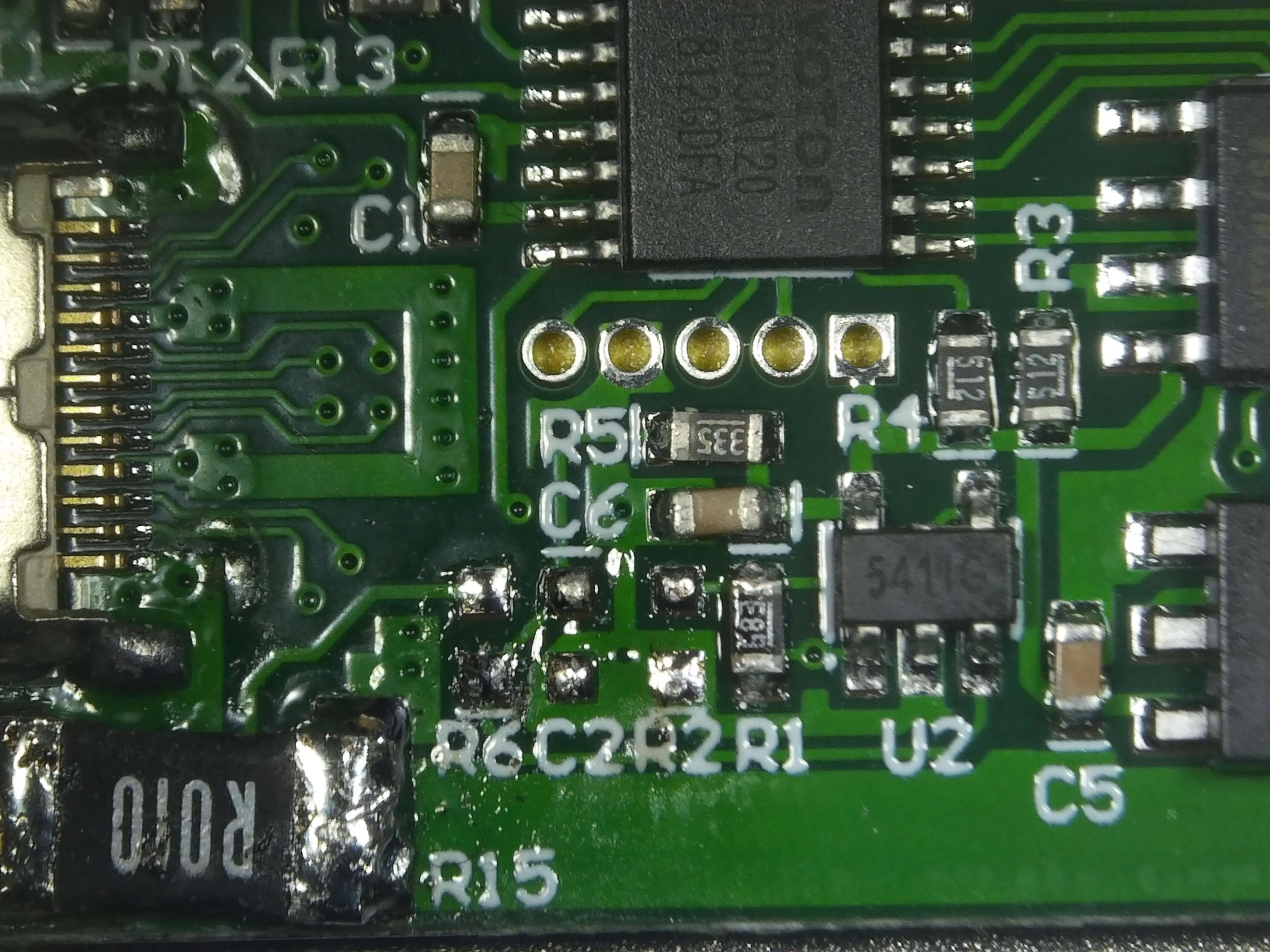
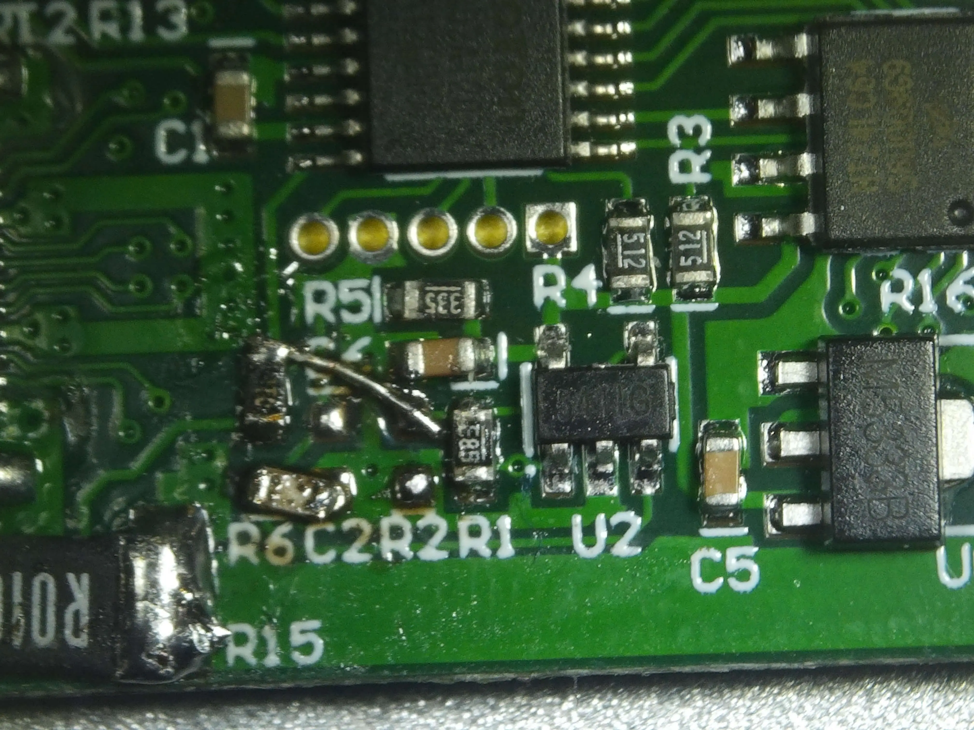
Inside of the cover of this device (4 small screws later), it is built rather neatly, with the current sense resistor in the lower left, the cluster of resistors to the right is the feedback for the op-amp to measure the current sense.
A small EEPROM is used for device settings and the main MCU can be seen at the top.
The signal path from the shunt resistor (R15) to the op-amp (U2) is fairly easy to follow. The load side of R15 is routed to R6 and the low side is routed to R2. Note that one half of R2 is the signal (top) and the bottom is connected to the local device’s ground as well. This does mean that once this modification is done the measurements on the screen will include the 19mA this unit takes to power itself.
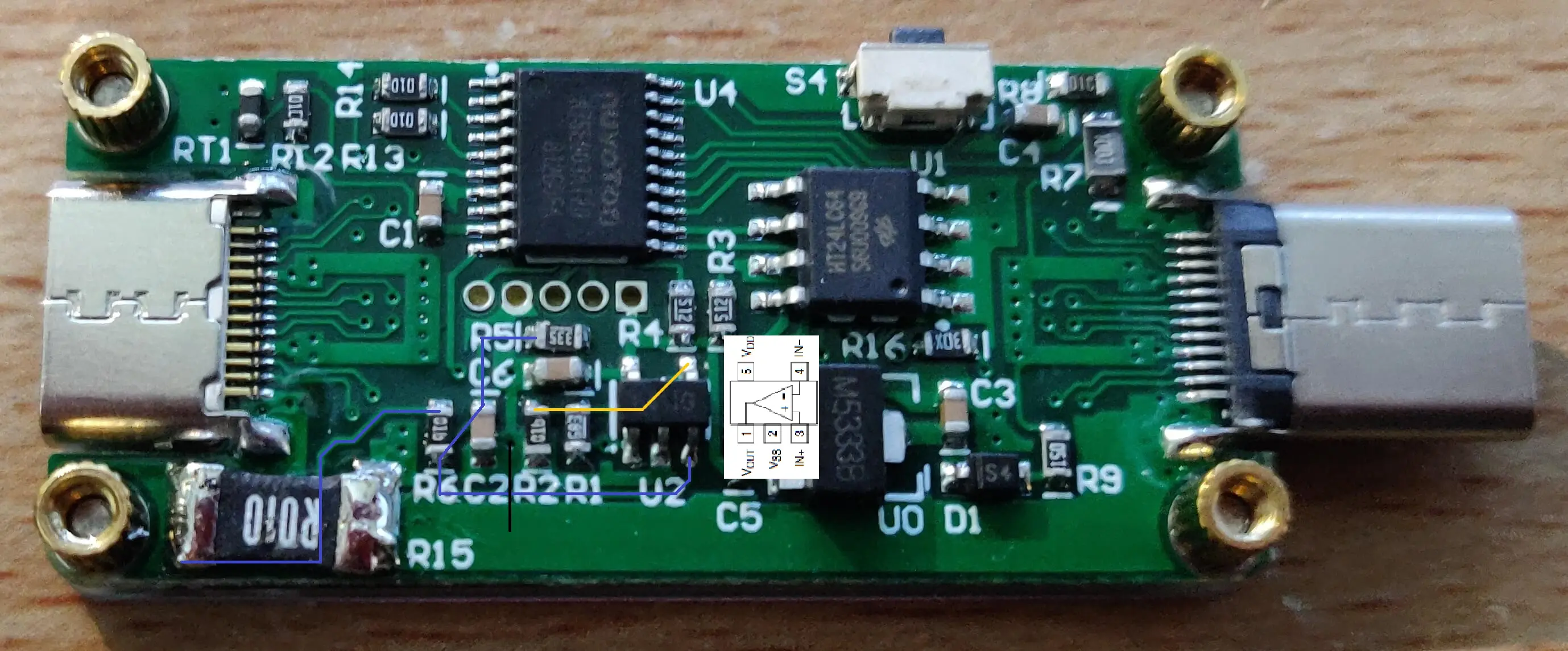
Signal Path Annotated
The above annotation shows the rough path taken by the signals. Where the purple lines show one side of the sense resistor and the orange shows the other side. I have also overlaid the pinout of the OP-Amp in use.
The Fix
To fix this unit and swap the measured direction, the easiest option is to swap which side of the sense resistor is fed to each of the two inputs to the opamp. Thereby reversing the direction measured.
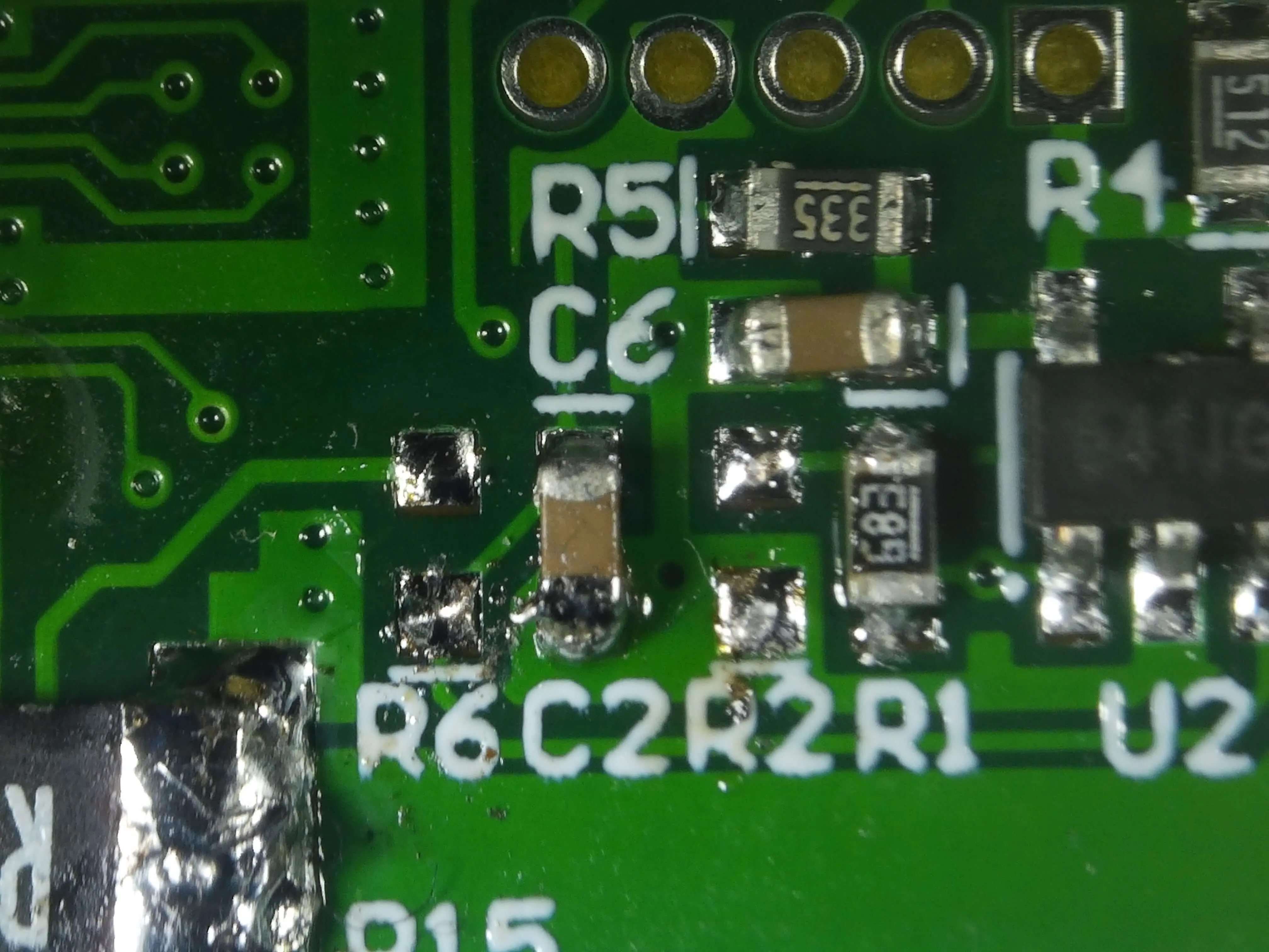
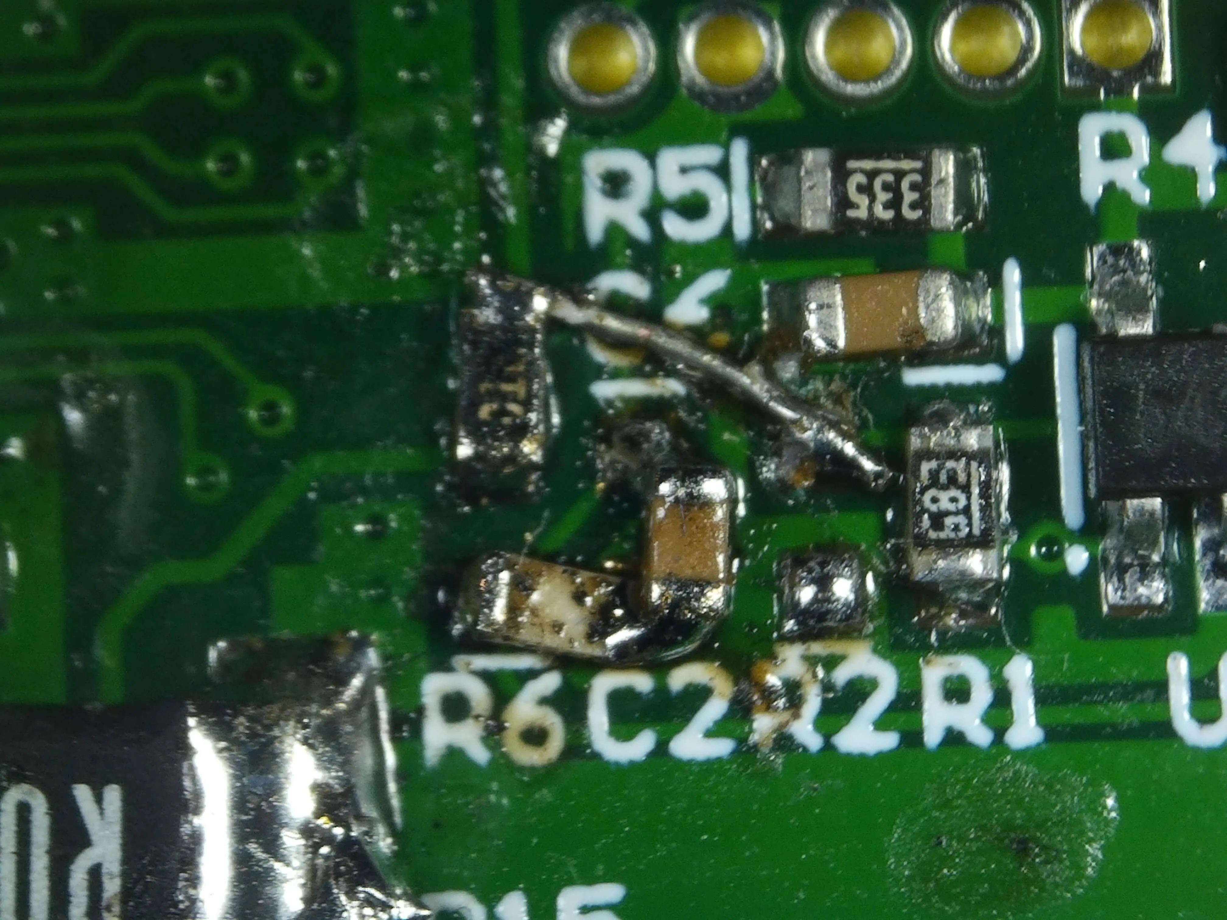
The resistors R6 and R2 are both 1k resistors inline with the measurements from the current shunt, by swapping the signal path using these is ideal, since they can be moved off location and then the signal can be re-routed.
Remove the resistors
Resistors removed
After removing the two 1k resistors (R2, R6) the signal path under these can be seen easier. R2 originally connected the negative input of the opamp to the local ground plane. R6 linked the positive input to the other side of the current shunt.
This modifications goal is to swap these two resistors in a crossover fashion.
Remove cap to make room
After removing C2, it is confirmed that one of the swaps can be done easily by using the bottom of C2, across to the bottom of R2.
Placed New Resistors down
After placing down the other resistor, a small piece of 30awg wire was used to link the other resistor into its home.
Done
And finally, replacing R2 back into its home finishes the modification. There is a mess of flux everywhere that will be cleaned up later on.
The usual wrap-up
As all good modifications go this one comes with a small trade-off. The unit now measures the current the other way around so it can be used easier for measuring the power consumption of the device you have connected. But it reads with an offset of 19mA that the unit itself consumes.
I personally don’t see this as a problem as its easy to ignore, and convenient when looking at power bank efficiency to know exactly how much you are drawing.