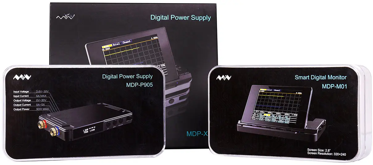
The MDP-XP combo
MDP by Miniware
This is an interesting idea, taking the conventional power supply system and giving it the “Miniware treatment”, which I like to think of as, a nice aluminium housing and a jump in portability. I have reviewed a few Miniware designs recently, and generally I have found all of their products to be a really nice premium feel and quality. Probably the lowest quality (and cheapest unit) is the TS100, which has become rather well known as a portable soldering iron.
The MDP is an interesting system, I’ve heard rumours of this systems existance for a while now (years), and every time the concept has evolved a little bit. When I first heard mention of this unit, it was a handheld switching regulator designed for powering small circuits, with built in controls. This concept has evolved into wirelessly linked modules that can be centrally controlled. With apparent plans for more types of modules that would intergrate with this system. (Hints of other DC power devices like programmable loads are floating around)
At launch price of $220USD (~$288AUD), this is a pricy set of devices. However, after using them for a while I see potential here to really perform and gain value for money. Both of the units have nice CNC’ed aluminium enclosures, which improves their endurance travelling in bags unprotected & and helps prevent damage. This case has the second use of being the heatsink for the regulator module, which helps prevent thermal throttling.
The internal’s of the system are well designed, with little cost saving, I have noticed significant effort being put into the system design to ensure the output is filtered correctly, and that the linear clean-up stage is kept cool. Later on I look at internal photos of the unit so how how the system is designed. It’s not a complex design, but it is implemented well. There appears to have been careful attention to the “quality” of the output, i.e. linear regulation stage that follows a pi filter to clean up the signal.
I have found quirks in the system, but so far all of these have been software issues. Normally these are infuriating issues to deal with that can drive users nuts. Knowing that Miniware will release the source code, I do not call these as big issues as typically either Miniware will fix the issues or when the code is open sourced, community members will fix the issues.
I have built up a wish list of things to watch / software changes I would like at the end of this article. I will try and come back and cross these off as they are fixed.
The manufacturers listing for this unit is here
Specifications
As this MDP pack includes two modules, I’ve listed their specifiations below for reference.
Screen module MDP-M01
- 2.8" Colour LCD Module (Looks like the typical ILI9348 style modules). On a hinge to allow it to flip up
- USB port for upgrading firmware and file transfer
- Two large encoders (like DS213)
- 5 Buttons below the screen
- 2.4 GHz RF module (NRF24L01)
Power Regulator module MDP-P905
- QC2.0/3.0 input on USB-C as well as 2.5mm DC Jack (Same input as TS100).
- 90W max power output (30V, 5A)
- 4.2-30V input (Testing indicates lower, but not spec)
- Buck-Boost DC/DC stage (output voltage can be higher than input)
- Linear output stage, reduces output ripple, and increase PSRR ratio.
- Can run standalone
- Coloured encoder wheel for control
- Reverse polarity protection on the input
- 4mm Banana jack outputs with Red/Blue indication LEDs
- Small white OLED display of current measurements / setpoint
- 2.4GHz RF Module (NRF24L01)
- P905 -> 90W@5A
Unboxing
The MDP-XP combo
When the pack is first received, it both units come packaged seperately, which is a nice touch and provides plenty of packing to ensure that they survive the trip unharmed. Taking both units out of the boxes, the following items were included:
- MDP-P905 regulator DC/DC unit
- 2x Silicone leads, Banana jack to crocodile clip
- Small USB -> 2.5mm cable for updating firmware
- MDP-M01
- Link cable to power M01 from P905 (2.5mm -> USB microB)
- Instruction sheets
Firmware
After unboxing the first thing to check is to go and grab the latest firmware from the forum, listed below. At the time of writing the firmware are V1.20 and V1.20.067 for the display and regulator, respectively.
Both firmwares appear to be the same, but sometimes the Chinese forum has newer software than the English.
Updating both units is done by plugging into USB while holding down the leftmost button (with text correct way up). Check the paper leaflet that is included with the units if you are unsure. I have found this to be a more unforgiving bootloader than the TS100/TS80, and I had to use my windows machine for this to work. If it doesnt work, try another computer (seriously, any AV can break it).
Appearance
Picking up the two units, its noticeable that both have a moderate amount of weight to them, similar to a large cell phone. This makes them feel very solid and premium. Of course this mostly comes from the machined case. However, this is a really nice feeling, and the thick case helps protect the units.
Both units feature a very well done, black anodised coating on the outside, with laser engraved labels for buttons, encoders, jacks etc.
The fold up screen on the display (M01) is a nice touch that is not often included on products on this price range. When using the items on a desk, its often nice to be able to angle the screen up slightly to avoid reflections or improve the viewing angle.
First time setup
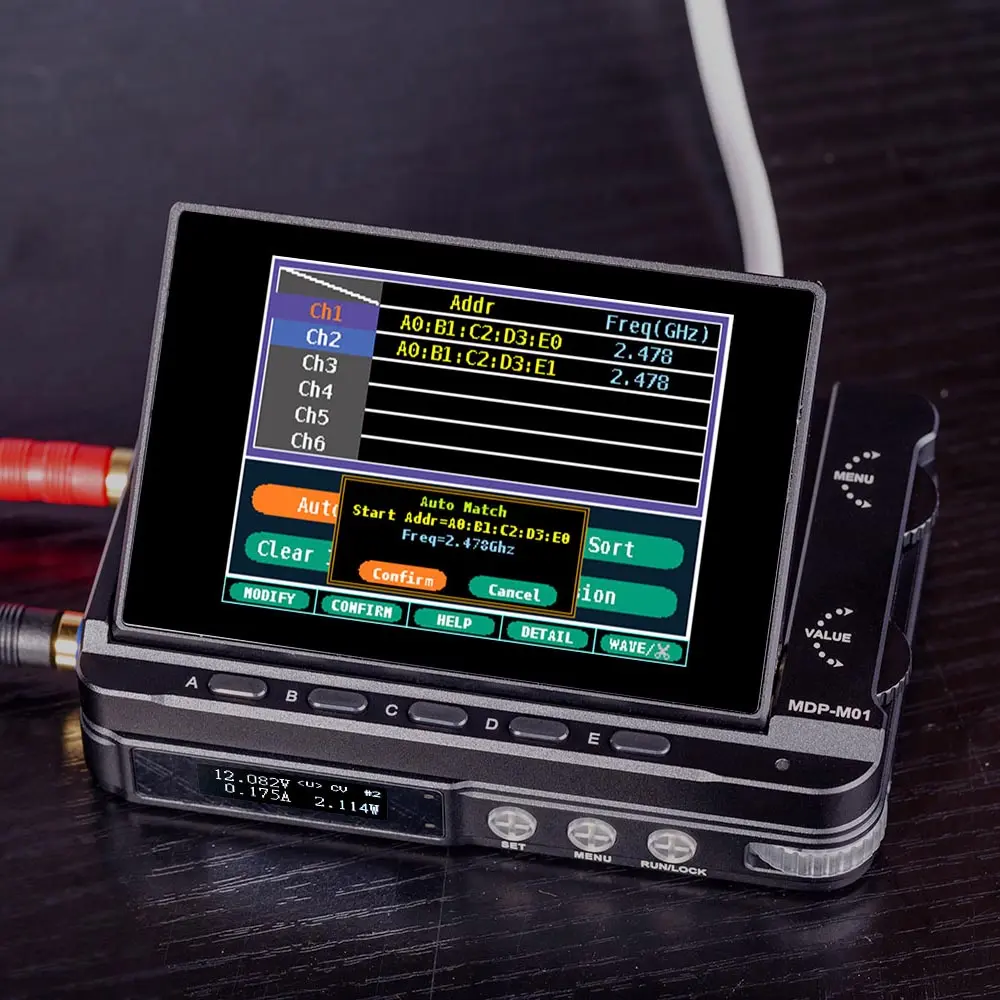
After unboxing the two units and sitting them next to each other, the first thing that has to be done is to pair the two units together. This is fairly easy to figure out, hold the MENU button on the regulator and scroll across to the rf settings. Pressing SET will then bring the unit into a pairing mode.
On the screen unit, pressing the settings label eventually gets to list of connected devices. Navigating to the auto connection option starts the display searching. Very quickly the display finds the unit and cancelling the search exits back to the main screen.
First time use
Once the regulator module is paired up, the controls on the main screen work and allow entering into the adjustment modes.
When you turn the regulators output on, the clear spacers around the output jacks light up and red and blue (to match polarity). This is a really nice touch.
The display unit shows the live output jacks reading in the lower left corner - even when the device is off. This is a really good feature to have as a sanity check when using it to charge devices or monitor whats happening. The regulator does not have a fast output discharge, so when turning the output off, expect it to slowly drop down to zero.
The regulator module works really well though, I have only managed to cause bad behaviour once. This is when its used with high current loads, its internal control loop that tries to maintain the DC/DC just above the linear regulator is a bit too slow. In this case I was testing by asking it to drive a Drill motor, and was having the unit start to oscillate as the over current limit kicked in and out.
This does not occur in any other tests I have run. I have performed the following tests without issue:
- Powering every development board I can find
- Powering LED modules in CV and CC modes
- Charging 1-6S LiPo and LiFe batteries (As high of an output as it would allow)
- Shorting the outputs to try and make the unit fail (Handles it fine)
- Backfeeding by connecting to other sources (No damage / nothing happens)
Running the regulator off a variety of sources, it generally seems to work. I tried pushing the lower limit of the input source down to around 3.3V and it still appear to work normally, so the spec may be concervative or it could change in the later batches. So you might be able to push this a little bit. Conversely, it does implement overvoltage protection and cuts out if you provide too high of a voltage.
The RF connection
At first, the RF connection seems like a needles complication that can be very frustrating if you need to keep the units close. However, it provides an essential function for no extra cost - isolation.
When using the RF link, and being careful to not touch the case of the regulator, you could float one module up above ground easily or use isolated supplies if stacking output voltages is required.
This can become quite neat, if you place an insulator between the modules when they are stacked, its easy to have them at very different potentials without having to worry about communications.
I have used this a few times, when its handy to have the screen in a easy to use location and then have the power supply running off a floating supply (usb power bank via USB-PD), and have it power an input to a device that needs to be floating from earth.
90W power limit implementation
One of the issues I have with the implementation of the unit, is that it limits you to the 90W very strictly when you are adjusting the setpoints. This can be frustrating when you want a “best effort” style of limit instead. This issue arises as it is a 90W limit, as well as a 5A output current limit. This means that, if for example, you have the output set to 30V, it will prevent adjusting the current limit higher than 3A to enforce the 90W limit.
This is fine, except for a few issues:
Firstly, it doesnt overly tell you why the adjustment suddenly stopped working. It would be nice to have it flash a small warning to remind you that you are limited because of the 90W rating.
Secondly, when using it to charge devices, it would be preferable to have it perform the 90W as a best-effort as it goes. So that if the device connected is pulling the output voltage down to 20V, it could allow up to 4A output, and taper back the current output as the voltage rises.
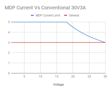
The MDP-P905 power limits
I would prefer instead, if the unit would allow me to set 30V@5A, but when I tried to consume, it would current limit if the output tries to exceed the 90W rating.
QC3.0/2.0 … Again
I have my grudges against the QC standard (or lack there of). However, it is nice to have if the other option is to only have the DC jack.
I would have seriously loved to see support for QC and USB-PD, it would have made using this device far easier in lots of odd spots. As people are using newer devices, USB-PD is becoming the norm. Being able to pickup a friends laptop charger to quickly power up a device and test is a very useful feature to have.
Thankfully there are USB-PD to DC jack adapters now such as these:
As QC3.0 typically has a 1.5A input limit, it would be really great, if when you were powering from QC, it would temporarily lower the DC input current limit to 1.5A. Therefore preventing the power adapter turning off if you overload its output.
Input current limit implementation
On the regulator module, you are able to specify in the menu an input current rating. This is great in theory, if you are powering the unit from a current limited supply (or just dont want to overload a power supply). However, this is implemented like a Over Current Protection (OCP), so when you exceed this limit by more than 20% it shuts off the output.
It would be preferable for this to act as part of the output regulation loop. So that when your input current is exceeding the specified limit, it would reduce the available output current to remain under this limit.
As it currently stands, you can set everything up nicely, but if at some point your load draws slightly too much it trips off, when it is normally much more preferable to have the output briefly current regulate back a small amount during the high load than lose power entirely.
Having a flashing screen or pulse the output jack LEDs under this condition could be a good indicator.
As mentioned above, it would be really handy to have this limit automatically adjust based on the supply being used. I power the unit from QC and PD, so I have the input current limit setup for PD (45W@20V), however, when using QC it is easy to overload the suppply without realising as it has a lower current limit. The firmware knows its running off QC as it has performed the negotiation already, so it could easily enforce a lower limit, or even store two limits (one for QC, one for DC Jack). This would be ideal as it keeps it user adjustable, but makes it easier to not overload supplies.
Using the components seperately
Using the two parts seperately is completely possible which is great, especially with the RF issues that happens when trying to use them together. Naturally the screen half is basically useless by itself. (But USB can pull off any screen shots you have taken).
Regulator module
The regulator module (P905) works 100% fine disconnected from the display unit.
Honestly, it makes a really solid little unit by itself. It’s an absolute pain to adjust current limits because the encoder doesnt have acceleration, but this is only a simple software fix. The hardware itself works quite well, especially concidering that this is fresh to market and they are still actively working on the firmware.
The hardware itself works really well, handling 90W loads for a few hours without any issue. It works really well in most applications, easily providing up to 5A (if its within the 90W limit).
Nothing changes at all when using it seperately except for the adjustments becoming slightly harder to do. When its off, its obvious if you are adjusting the current or voltage limit using the wheel. Pressing the set button will toggle between which one you are adjusting.
When the output is turned on, the live readings replace the set points, you can adjust the setpoints live as well. There is a small indicator on the screen that looks like “” or “” that shows what the wheel will adjust when you move it.
I reccomend using the lock feature if there is a chance for this wheel to be moved accidentally.
Using the system as a whole
Overall, the system works really well together, when the two units are stacked together it feels quite natural, and the tilting screen is a really nice touch. I have found the RF can fail in noisy environments. I tested the unit in a very populated area (ble scan shows 200+ devices, 20+ WiFi networks nearby). In this case the screen was failing to work with the power supply module. However, the power supply module by itself did work.
I have enquired and this is sort of expected due to the limited range of the RF modules due to their pcb antenna and being inside of an aluminium enclosure. However, I have posed feedback on better ways to handle this. I believe this will be fixed, and if its not, when it becomes open source I will fix it.
Analysis
Linear Power Supply Unit (MDP-P905)
Logic Board

MDP-P905 Top board
Opening up the linear power regulator module reveals two seperate PCBs. Attached to the upper board in the picture is the main MCU controller. This is using (yet again) and F103 as the main microcontroller in this system, however, finally this is in the larger LQFP100. Interestingly there is an extra SPI flash, which is where I hope some datalogging will eventually be saved to. The extra flash provides some good options to also support saving presets and waveforms etc from a computer. I’m thinking about a future firmware modification that would allow downloading waveforms etc via the RF interface, using the monitor units USB link to push these to the regulator.
The radio module is mounted as a seperate module to this PCB, which is great for service and modding opportunities. It does however, look a little like its only supported by the solder at one end of the pcb. I hope that there is glue under the module… Though if your RF fails, this might be why.
Power supply board
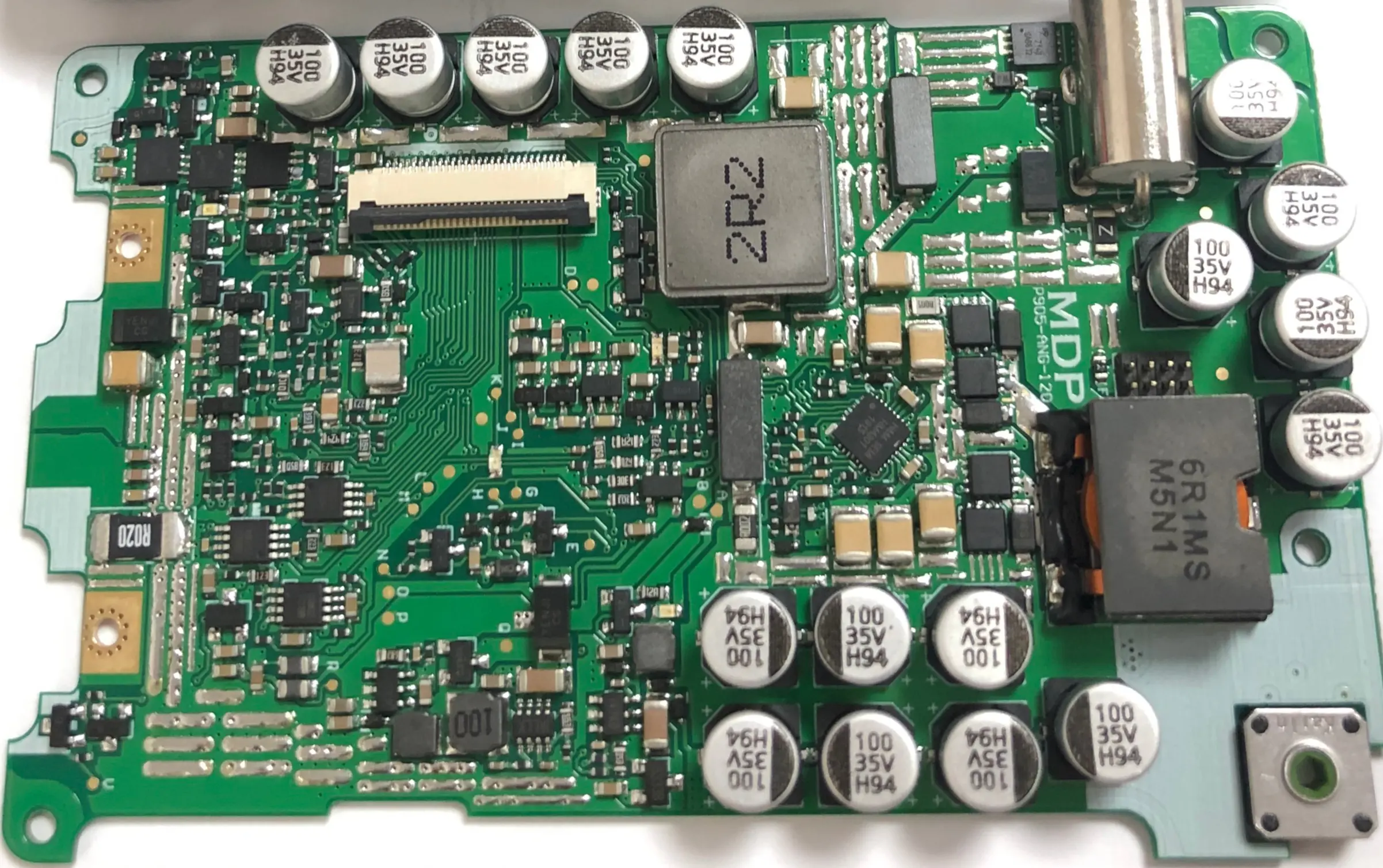
MDP-P905 Bottom board
A really nice touch is all of the test points on the linear power supply are generally labelled.
The design looks to be a Buck-Boost DC/DC regulator stage followed by a descrete linear regulator stage. The DC/DC regulator is a HM4301. This is a really interesting IC, as it allows for PWM (10-100KHz) control of both output voltage and current limit.
Following the circuit layout, the DC power enters in the top right, flowing through the DC/DC stage to the bottom right. There is a current shunt and jumper in the middle of the board (vertically oriented), which then takes the DC/DC output to the top middle section of the PCB and cluster of filter capacitors. This is done via a 2.2uH inductor to remove a large portion of the ripple from the output.
The left side of the PCB appears to be a linear regulation stage, and current limiting stage. There are large mosfets in the upper left of the unit, and there is a small current shunt in the lower left, near the mounting hole for the negative output terminal.
Its worth noting that the output terminals are connected to the PCB via screws, which should provide an excellent connection path while maintaining easy opening of the unit.
Also, note that the large inductor used by the DC/DC is heatsinked to the top shell, and there is an NTC thermister near this inductor. This is excellent to prevent damage to the unit in an overload situation.
The DC/DC regulator control chip is the HM4301, which is a nice looking control chip designed for this kind of use. It uses two PWM inputs to allow for digital control of its output voltage and current which is ideal as the STM32 has high resolution PWM timers ideal for this usecase.
It is of note, that there are seperate fuses for the DC jack and the QC port!
There are 4 LEDs on this PCB, I have not yet run the unit with the case open to find out what these are used for, but its highly likely that these will be a great help if you damaged your unit and are diagnosing the failed part.
Issues
Hardware
- Damn QC3 input and no USB-PD (No CC pull down either, so PD wont work at all)
- Weak RF range - cant separate the units in noisy environments
- Annoying 2.5mm connector for usb on the regulator module
Firmware
- Voltage collapse issue due to control loop speed
- Units do not handle intermittent RF connection well
- Graph on the display unit is harder to use than ideal (No rolling mode)
- No data streaming method to PC (Would love it if regulator could stream measurements & control)
- Encoders have no acceleration (on regulation module, holding set increases change speed though)
- Encoder on the regulator is always lit white rather than using the colours
- Sometimes QC negotiation doesnt work
- If software crashes on the regulator is stays off because of the soft-on function
- OLED on regulator is only 1Hz refresh rate
- The way the 90W limit is enforced
- The way the input current limit is enforced
- Automatically adjust the current limit if using QC to power the unit
Future
There are future plans in works at Miniware to expand this product lineup, by creating more modules that integrated with the M01 display. Their website mentions the following modules:
- Digital Signal Genetator Module
- Electronic Load Module
- Power Charger Module
- Battery Pack Module
I think this is a really good idea, and also, knowing these will be open source there will probably be mods / software tweaks for all of these. The potential to mess around with these devices and push them to perform in roles they were not designed for is fun. Looking at how much the alternate firmware for the TS100 has pushed the stock firmware along too, it has created a better ecosystem for these devices than they would have had otherwise, and that I believe is an excellent thing.