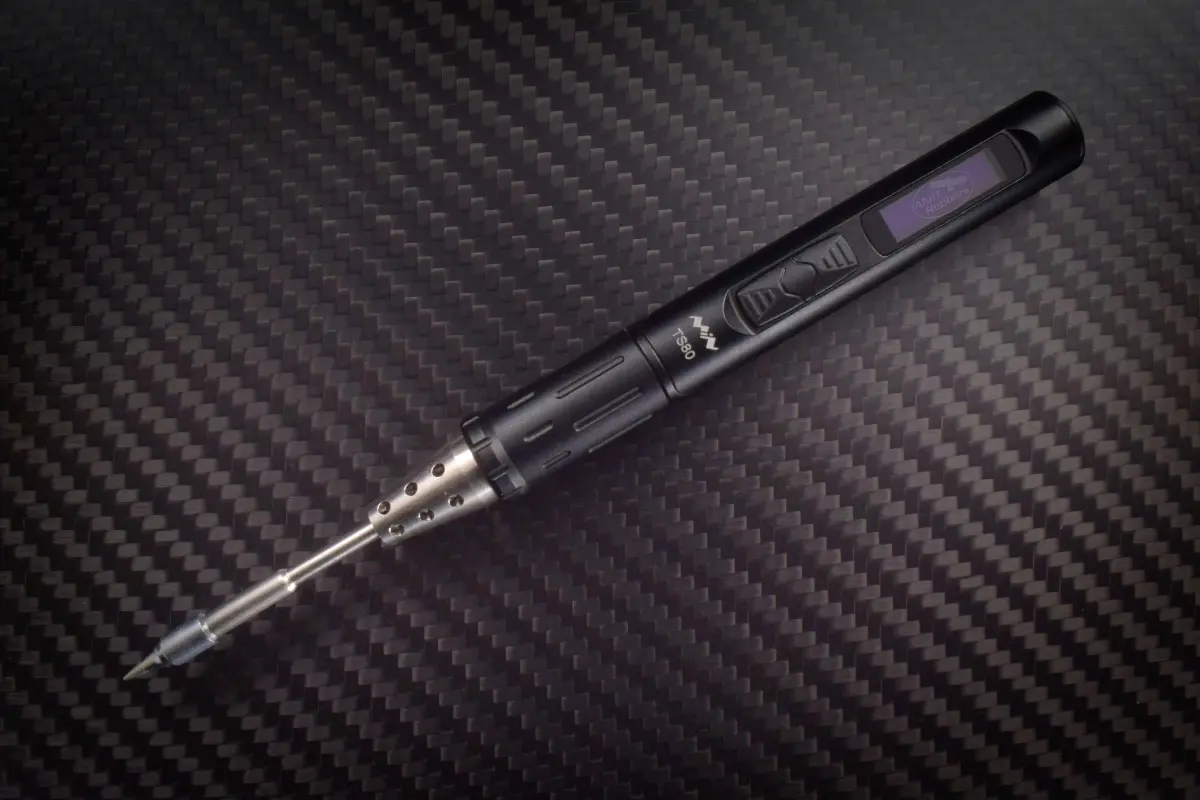
The TS80
TS80 by Miniware
The TS80 is an interesting spinoff from the TS100. Origionally called the TS200, it was intended to fill the market gap for an even more portable solution for soldering in the field. The soldering iron is designed to be powered using QC power banks at either 9V or 12V. The markings on the unit state 9V 2A (~18W). Which is a really low wattage for a typical soldering iron. This does show up in the units struggle with large components and its slower heating time when compared to the ~40W+ that the TS100 typically uses.
Power
Officially on the packaging the unit only supports the 9V mode of operation, but in discussions with the manufacturer, the circuit can support up to 12V fine. This opens up opportunities to allow for driving the unit a little harder than specified to push the boundries of what can be done wih the unit.
I would like to note that even at the stock 18W of power, the unit is more than capable of quick repairs, SMD rework and actual general use.
In the stock firmware, the iron measures the resistance of the tip, and depending on the measured value, calculates the ideal voltage to request from the power supply to ensure the power supply is not overloaded (assuming an 18W rating which is typical of QC). This works as QC3.0 allows for the voltage supplied to be adjusted in 200mV steps.
Quick charge
Quick charge is privately documented protocol that has been reverse engineered from scratch numerous times. It is a very simple protocol at its heart, using just two voltages that are signalled on the USB D+ and D- pins. It is optimised to require minimal hardware on the devices at each end of the cable (generally 4 resistors).
Entrance Sequence
Normally when most chargers start up, the USB data pins are “shorted together” to conform to the fast charging battery specifications. To enter into the QC mode, the device must set both data pins to 0.6V, and hold this for 1.25 seconds. After the 1.25 seconds, the charger will disconnect the two pins and add a small pulldown to D- to indicate that it has entered in QC mode.
Pin voltage codes
Officially, the following [D+/D-] voltage levels are supported in the QC Spec:
[3.3/3.3]= 20V (Not often supported)[0.6/0.6]= 12V[3.3/0.6]= 9V[0.6/GND]= 5V[0.6/3.3]= Continious Mode
Continious mode
This mode allows the output volage to be adjusted in 0.2V steps. Both up and down. Typically this covers the 4V-12V range. Once you enter into continious mode, no other voltages will work, until you enter 5V mode, which exits QC and you then have to re-enter.
When in continious mode, “pulsing” to 20V mode will increase the output by 200mV, and “pulsing” to 12V will decrease the output.
Why its not actually a standard
The number one issue with QC, is that its standard is not open, so all of the vendors have decided to implement it just slightly differently.
As far as I have been able to divine from measuring existing systems and reading documentation found online, I believe the above to be correct. However, this system does not work on all power banks, with some acting slower and some faster than the standard.
I really wish that Miniware had integrated one of the many off the shelf IC’s that can negotiate for USB-PD as well as QC. As, QC is fairly common on power banks, but more and more people are adopting laptop chargers that can use the USB-PD style of power negotiation. Having support would have been ideal for situations where I’m already carrying an adapter for recharging my laptop.