Outline
This is a half walkthrough / half hints guide to taking a base concept for a STM32 from idea to (somewhat) working hardware. The goal is to roughly document the path I use, but not bogging down into the details on things that are easier to google.
For this series, I’m looking at designing out a small development board, designed to mount to the quite nice ILI9486 LCD unit. I’m designing this mostly so that its in a nicer form factor than other development boards, and so I can use USB-C as I really dislike USB mini-B.
Selecting the main MCU through requirements
Core requirements for this board is to breakout useful peripherals nicely, along with the LCD and a battery charger solution. However, as I intend for this to be flexible for a few different projects, I would like to breakout a selection of the peripherals that are often required for various projects
Rough requirements
Normally I would either write these down on paper or use a spreadsheet to track these.
- 4.2V Lithium battery Charger
- USB Full speed (12Mbit)
- ILI9481
- SPI
- 1-2 UARTs (with control pins)
- UART Bluetooth link module
- PWM Output
- ADC Input(s)
- Soft power on off (no slide switches)
- I2C
- uSD slot (if it fits)
- SWD debug and SWO if possible
- Ability to access SPI flash on the LCD
- LCD touchscreen support
Device Slection
I use CubeMX from STM to narrow down the list of possible parts for selecting which devices to use. When you open CubeMX, and go to the new project part selector, you can use the filters on the left to narrow down your devices based on criteria.
Converting the previous list of requirements into peripherals :
FSMCfor the LCDSPIx2 for the Touch screen and external SPIMMCorSDIOfor the uSDUSB DeviceorUSBfor the USB connectionI2Cfor the external I2CUARTx2 for the external uart + Bluetooth
Other peripherals such as the ADC and debug connections are present in basically all chips so dont help filter this down.
Next, there will be an absolute bunch of devices left. I reccomend filtering the package types to remove BGA and hard to solder packages (I like TQFP and QFN).
This should narrow down the device list a fair bit, to reduce from here I search on my selected store what I would be buying from the look at an appropriate cost point.
For this project I dont care about saving a few mA of power usage, so not worried about selecting an L low power varient.
Noting now that with the STM parts, the letters in the part names do matter, and also follow fairly logical naming schemes for varieties. This means you can quickly scan this list and spot the pattern of devices that would work for your application to narrow down the search.
Selection results
After narrowing down the results, for this project I have selected the STM32F407ZETx as this chip is both common and easy to buy, along with there being other development boards for this cheap so its possible to sanity check against these.
Pinmapping an check it all works
Now that for this project we have decided upon the device to use (STM32F407ZETx), the STMCube software drops us into the pinmap and peripheral configuration flow. STMCubeMX View
In the STMCube software, the general order is to enable a peripheral on the left, check its pinout on the right works. Then setup its settings.
I highly suggest messing around for a little bit here to get a feel for it.
Note: some peripheral pins can be located in multiple locations. To move a mapped pin to an alternate location, hold control while clicking on the pin and other locations will highlight in blue. You can then drag the pin to these locations to move it
Order of mapping
STMCube will automatically grey out and disable peripherals that cannot be enabled as there are no pins that can be used for this peripheral. To make life easier, work through the order of enabling peripherals in order from most options to least. For example, as FSMC and SDIO have very little options to adjust which pins are selected (you cannot move them often), enable these first. Then for things like UARTs where there are 2+ peripherals, do these last as you can change to UART2 if UART 1 is taken for example.
Also note, if you dont pin signals to a pin, STMCube will shuffle these to make room for new things you enable. This is not a big deal at this stage in the design, but note this and dont panic if it occurs. (It will).
Suggested order
In this case, for this design I map the pins out in the following order:
- FSMC
- SDIO
- Debug (has no alternate pin maps)
- Crystal (has no alternate pin maps)
- USB (FS device has bootloader support)
- I2C
- SPI
- PWM
- UART
- ADC
- CAN (if it fits)
Setting up peripherals in CubeMX
Before moving on to the PCB schematic capture, it is worth working through the peripheral setup and making sure you can setup the peripherals how you want.
Turn on IRQ’s
Even if you dont plan to use IRQ based code for the peripheral, often its easier to turn it on and not worry about it :). Just tick the box to enable the IRQ for now.
Turn on DMA for the devices that you require it on
I highly reccomend using DMA on all of your peripherals that you can. If you run out of channels in your design, you can try alternate peripherals (ie try a different UART if its channels are available). If you are really short of channels, remove them from peripherals where falling back to interrupts is not an issue (I2C is a good example here, as its DMA isn’t amazing). UARTS if they are slow or not often used are also good cases to move to IRQ’s. Debugging output UARTs usually fall first to be being pushed back. Also if you know a peripheral is predominately used for transmit (again debug outputs), dont attach a DMA to the recieve at first.
Setup middleware
For this design, I’m planning to use FreeRToS to manage some threading in the system, so at the bottom of the middleware list, enable FreeRToS and setup as much as you know now (so that the generate code is as close as possible).
For the uSD card, I’m also enabling FATFs support into the build as well, so that the generated code is setup for both FreeRToS and the uSD slot. This code often isnt perfect, but its often very close.
Tips
I highly reccomend planning your pinout with regards to your PCB. Try and group peripherals and pins logically to make the PCB layout easier. I.e. Group pins that are going to be the same module where possible. In this design, I inspected what was possible on each pin by clicking on it. Then the highest density of peripherals I wanted to break out were located in the lower left of the IC. For this reason I grouped these connections in this corner
Final Pinmap
This is how the final pinmap works out for this design.
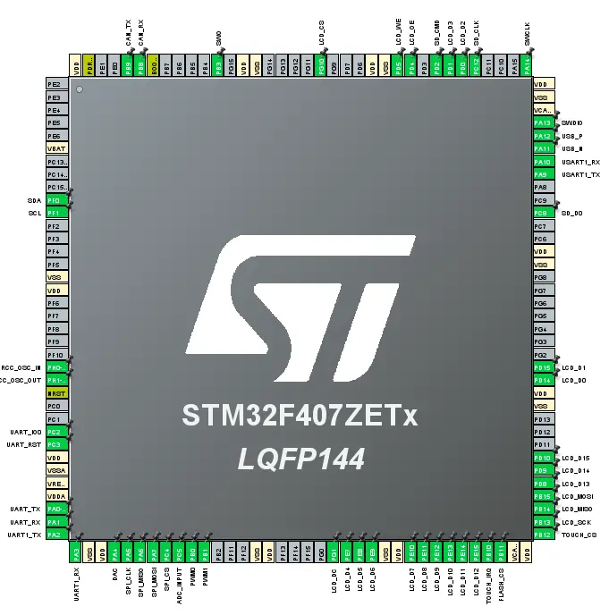
Final Pinout in STMCubeMX