The WS2812 aka the Neopixel is a very well know LED, it combines a fully self-contained PWM driver ic with RGB led’s in a cheap and (relatively) painless to work with package. The downside to these is their not-very-fun protocol that requires effort to ensure you drive it at the correct timing.
Other fantastic people have already done a deep dive into this protocol.
The TL;DR is that the protocol works out to encode the bit as 0 or 1 based on the pulse length, with minimum off times between bits. Otherwise, there is a very long off time to latch the data and reset the state machine. Thats it.

Relative timings of 0 and 1 bits
The downside is that this protocol enforces fairly fast (a few hundred kHz) pin toggling rates. This means doing it without using interrupts, timers or other hardware requires precise timing code that is often not portable.
Sending the data in the right format, every time
To send out this nice sequence of pulses for the LED’s there is a lot of existing code on the internet.
I highly reccomend reading through the NeoPixels Revealed blog, as it has by far the best description of their protocol.
And naturally, like all good things online, here is yet another approach.
The two-step combination this uses is the previously documented Timer+DMA combination. This uses the DMA engine in the microcontroller to handle sending out the pulses for each bit. But at the end of each bit period, the DMA will copy the timings for the next set of bits into the timer.
Both of these actions (Timer and DMA) do not consume any CPU resources (though they do tie up the internal bus a bit).
As these timings are per bit, this would require a buffer that is 3*8 samples long for every led, which is a lot of memory to dedicate to the task if you are running more than a few LEDs.
To avoid the need to have huge buffers for the DMA, the processor can be set up to handle an interrupt once the DMA is halfway and once it is at the end of its buffer. This allows the processor to fill the half of the buffer that has just been emptied.
Using the Timer and DMA in a loop like this does mean that by default, the device will send LED data all the time. Depending on your application you may want to stop and start this process to reduce the processor time used by the interrupts. Doing this is fairly easy, but it is something to be aware of.
How does this work
At the beginning of time, the timer will count up from 0 to its maximum value. For the sake of the example, we will use 10 as the maximum number.
Once the timer counts up to the maximum, it will roll over back to the beginning (0). When this occurs, the timer will create an “update” event.
This event is only triggered on this roll over event.
When this event is triggered, it is set up to route through to the DMA controller.
Timers
The timer peripheral is excellent at making pulses for us. In the PWM mode, it will create something that looks like the following figure.
The output will start on (1 / high) and then once the timer count reaches the set point for that channel it will change the output to be off (0/off).
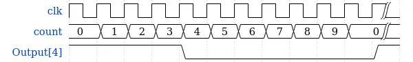
Example PWM pulse for 4/10
DMA
DMA controllers look scary as weird objects. But they are just fancy memcpy engines, that uses its own tiny state machine processor rather than the main CPU.
DMA breaks down to the following state
- Wait for an event
- Read data from a location
- Write that data somewhere else
- Optionally increment the read, write or both locations
- Decrement the counter for many times it should run
- Go back to 1
In step 4, the DMA engine optionally can increment the pointer it has for the source or destination. This allows one of these two locations to reference an array and have the DMA engine walk through the array automatically.
The simplest implementation
Timers can send a single pulse for a bit, very accurately, and without the CPU needing to do precise timing. However, they can only output one waveform. Using the DMA engine, on each cycle of the timer, the DMA can load in the next bit’s timing to the control register. To prevent there being a race condition on this data movement, the timer features a pre-load function. Which holds all register changes back until the timer rolls over the next time. This means that the DMA engine is running one cycle of the timer behind. This feature also means your internal bus can have a little bit of contention and data should make it in time. (Remember this signal is in the kHz, not MHz.)
The simplest implementation of this is therefore to use the DMA to push data from a pre-computed array of bit timings, into the pulse width control register (CCR) of one of the timer’s outputs.
To illustrate this simpler implementation, here is a nice confusing timing diagram.
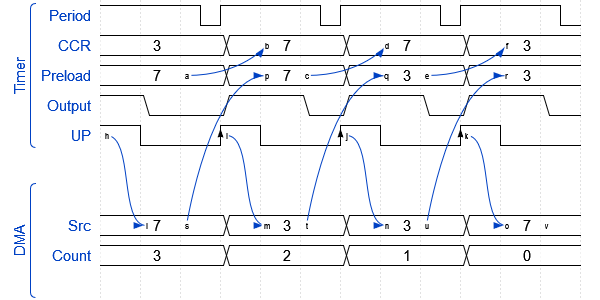
Data movement for timer preload and DMA
The mildly overwhelming diagram is relatively simple if taken a step at a time. At the beginning of time (the left side), an event is triggered by the timer on its UP event, this is from the counter rolling over. This event is routed to the DMA controller, which will copy one byte from its source array into the CCR registers preload and then decrement its counter. At the next timer period the preload register is copied into the CCR (sets the output duty cycle), and it also fires off another event to the DMA controller to copy the next value.
This process will continue until the DMA count reaches 0. At this point, the timer will keep going, but no new data will be loaded into its control registers.
At the time when the DMA count reaches 0, an interrupt is fired to the main CPU core, and it can choose how to act.
The downside of this simplest approach is that for every bit in the data to be sent, 16 bytes of ram will be consumed for the DMA controller buffer. When only running a small number of LED’s this can be acceptable and it keeps the code complexity down.
The code for this would generally consist of:
- Pre-compute into ram the bit timings for the data to be sent
- Setup the DMA controller to copy the data to the timer
- Start the timer
- When the DMA finishes, stop the timer, and hold the IO pin low to send the latch signal
Scalable implementation
The main downside to the simplest implementation is that the ram required grows linearly with the number of LEDs. If you are also storing in ram the values for the LEDs the ram is now growing exponentially (well n^2, but it’s still bad).
To reduce the ram consumption of the driver, the processor can use interrupts from the DMA controller to on-the-fly compute the data.
The DMA engine generates interrupts when it has emptied half of the buffer, and at the end of the buffer.
To utilise these, the DMA engine is put into continuous (or circular) mode.
This makes the counter for the DMA engine act like the timer, where it will reset to the start once it hits 0.
Using these interrupts, the processor can continuously fill the DMA buffer and keep ahead of the timer as it consumes the calculated timing measurements.
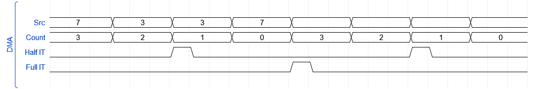
DMA Half and complete interrupts
In the timing diagram above, the two interrupts from the DMA engine trigger alternatively. When each of these occurs, an interrupt on the processor can fill the half of the buffer that has just been emptied.
This allows transmitting the timing using a significantly smaller buffer, only large enough to hold the minimum number of values. There is naturally a tradeoff. Smaller buffers require more interrupts, but each interrupt will involve less work to fill the buffer. Generally, larger buffers are better as less time is wasted in entering and exiting the handler. But these have the tradeoff of longer time the processor is blocked in interrupt handling. A buffer of two LEDs has so far worked out a sufficiently good balance point.
The basic code for implementing this would be along the lines of:
void fillSection(uint16_t *buffer) {
    //Fill half a DMA buffer worth

      int startPos = currentLED * bytesPerLEDChunk;
      int bufferPos = 0;
      for (int bytePos = 0; bytePos < bytesPerLEDChunk; bytePos++) {
        uint8_t b = rawrgb[startPos + bytePos];
        for (int bitPos = 0; bitPos < 8; bitPos++) {
          uint8_t bit = (b >> bitPos) & 0x01;
          buffer[bufferPos] = bit ? 7 : 3;
          bufferPos++;
        }
      }


    currentLED++;
  }
By calling this code on each half of the DMA buffer, in the interrupt handler, the CPU can fill the other half of the buffer.
Scaling further
The key limitation to the more scalable implementation above is that each timer is only able to drive one string of LEDs. While the daisy-chain nature of these LEDs means that generally, one string can run all of your lights, in your application it may be easier to worth with multiple sets of LEDs. For example, if you have four similar objects that want to lit in similar ways, it can be nicer to not have to worry about wiring between the strips, but instead to run the signal to them independently.
Also, every extra timer and associated DMA channel that is used will require more interrupts to the processor. While total CPU consumption will be similar, having fewer sets of interrupts occurring at once allows more consistency in timing and reduces the risk of an interrupt running over time and not filling the DMA buffer fast enough.
Being able to use all four channels of the STM32’s timer would allow for driving four independent chains of LEDs at once, using only one interrupt. This both reduces code complexity and keeps more DMA channels open for other hardware.
Using one DMA channel with multiple channels
The DMA system can only copy one value for each event it receives.
To work around this some (select few) peripherals support methods of causing multiple DMA events instead of one.
The second issue is that to write to the four registers in the timer (four channels, each with their own Capture Compare Register (CCR)), the DMA controller would need to use address incrementing on the peripheral side. The DMA engine only supports incrementing the address on each write, with the only reset on the counter rollover. This would require the DMA engine to only copy to the four registers and then the buffer would require refilling. This would require an interrupt to the CPU after every bit (cycle of the timer). Which is nearly as bad as using interrupts for all of the IO.
Fortunately, some of the timers in the STM32 lineup has a feature called DMA burst. This is a special setup in the timer that provides two features to work around both of these limitations.
First, it provides a special register, that can be set up to access a “window” of registers in the timer. This means that after the update event this will point to the first CCR register. But once that is written, it will move to point to the second CCR register and so on. This will reset after a predetermined number of writes have occurred.
This works alongside the other feature that allows configuring multiple extra events to be generated automatically from the one base event.
So, by setting the timer up to generate three extra events, and setting the window to point to the first CCR register, every update event will now trigger four sequential DMA writes to occur.
This feature is designed for doing exactly what we want to accomplish!
To utilise this feature the timer has to be set up to create three extra events, and to point the window to the CCR1 register.
This is configured in the DCR register. For this example it would be a value of 3<<8 | 13. This corresponds to the three extra events, and the CCR1 is the 13th register offset from the base of the timer. This is outlined well in some of the reference manuals. When creating the test project for this, I found that the newer STM32 L4 series have a more in-depth description. But the features and registers are identical.
Finally, demo code for the multi-channel optimised version
The demo code was developed on one of the so-called “Black Pill” development boards. These feature a STM32F401CCU6 processor, which is quite powerful for the price and its Timer1 has all of the features required.
The demo code for this project is available on my GitHub over here.
Specifically, the driver code is here.
An initial naive implementation of this code stored the data for the four channels in an easy to use order of storing the RGB values for each led in order in the lookup array. This has the downside that the interrupt handler has to do the unpacking of the bits for each led in interrupt time.
A slightly more complex to debug but the more efficient scheme is to do all of the bit manipulations ahead of time when setting the colour for each led instead. As this defers the logic into the led colour setting code, which is called at a much lower rate, less CPU power is used overall. In testing, this resulted in a 50% reduction in time spent in the interrupt handler.
Note that this code will easily emit 250 updates per second to short led chains.
To use this code as-is, LED’s will need to be connected to the timer one pins on A8, A9, A10, A11. Additionally, the GPIO A12 is toggled high while in the interrupt handler to allow using an oscilloscope or logic analyser to measure the computation time.
The key things to set up when using the STM32’s timers like this, outside of the driver class are:
- Setup the timer tick rate and rollover count correctly
- The total period should be within the time allowed for a
0bit + required low time. - Generally, you want the total period as long as you can if you want low CPU usage, or as short as you can for faster update rates
- Setup the DMA to run in circular mode
- Remember to enable DMA events in the timer (STM HAL currently doesn’t do this for you)
- Use the DMA Burst to your advantage
- You may need to edit the timings in the library to suit your timer
- It’s harmless to send data for more LEDs than you have :)
Also: Finally, huge shoutout to wavedrom, which makes all of the diagrams on this page super easy to generate.