As is relatively well known, both the Wii and Wii U have extremely limited power output on their USB ports. Nintendo appears to have limited these to exactly the 0.5A of USB 2.0.
As the Disk drive in my Wii U has started to become intermittent at reading disks I went through rapidly backing these up to an external hard drive to prevent the device from effectively becoming a brick. However; using any external drives requires either a Y power splitter cable or externally powered drives. While functional it’s certainly ugly.
Ergo, to work around this I bypassed the power limiting circuit on each port. This is mostly a small post for anyone else wanting a reference for one method of doing this. (And as a record in case I forget how to do this in the future).
Please note that of course, this removes some protection on these ports, so don’t plug un-trusted devices.
Step 1: Tear down
Tear down the console until you are down to the base motherboard. I recommend the usual iFixit instructions as always for the teardown. One difference on my unit (Maybe that mine is a later model; or AU quirk or similar) is that the bottom shielding is trapped under the mounting plate for the CPU heat sink. So your disassembly may vary but iFixit covers all the main info.
Step 2: Bypass current limiters
The current limiting ICs near the USB ports are fairly easy to locate. The circuit design appears to be laid out with large filter caps followed by a power limiter and then an inline inductor.
I decided to bypass all of this by jumping directly from the filter caps to the far side of the inductor. Mostly as I do not know the current limit of the inductor and I don’t feel like opening the console again.
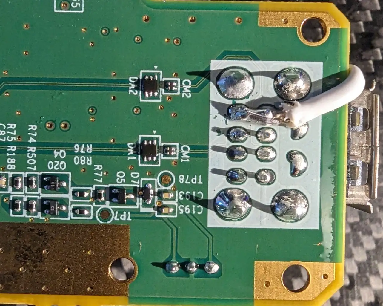
For the front USB ports, I scratched off the solder mask near the USB port to gain access to the 5V traces on the USB ports. The connection points have already been tinned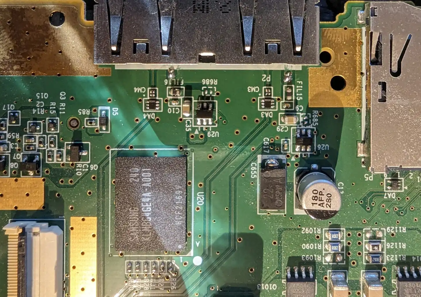
The 5V filter caps are nice and close by to easy to run wires to. I used far too thick of a wire here, but it was the least overkill wire in my spare parts bin at the time. I also strongly suggest fixing the wire in place with something, in this case, I’ve used UV set epoxy to lock the wire in place and also insulate the exposed wire. When soldering to the cap, you need to be wary of the small vias nearby, I’m sure shorting 5V down them will cause problems.
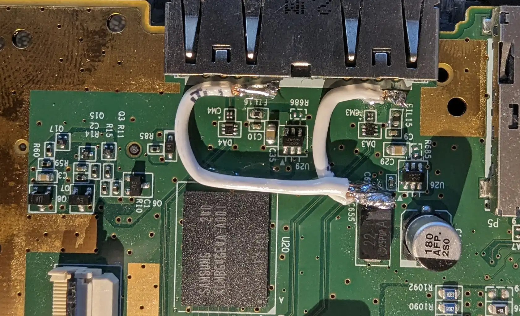
The wire is definitely overkill
For the back USB, I ran a cable around the edge of the board as wasn’t sure about VIA current rating. If I were doing this again; it’s honestly probably fine to run to the outside of the inductors.
The wire can easily be attached to this capacitor The wire goes directly to the USB connector
Step 3: Reassemble and test
When I first reassembled my unit it did not power up correctly and a faint clicking could be heard. This is caused by not re-connecting the disk drive correctly. Just open the device, and connect the drive connector carefully to keep it straight. Then the unit boots and works perfectly, and external 2.5" drives can be powered happily now with a stable connection.