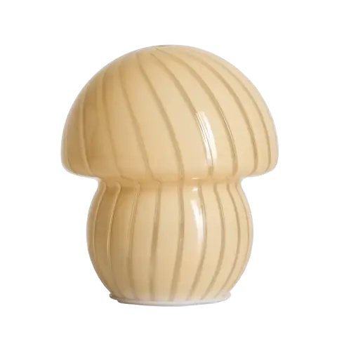
The KMart Mushroom lamp looks great,and is reasonably priced. However it suffers from the greatest sin of all dimmable lamps; pressing the button goes UP in brightness. This means that whenever you want to turn the unit off, you need to be blinded.
This alone is a reason to replace the controller, however giving it smart controls so I can tie it into Home Assistant is an extra win.
A note is that these lamps cheaped out the rounding-error cost of the resistors for the USB-C CC pin’s, so you have to use a USB-A to USB-C cable with them.
What You’ll Need
Hardware
- Kmart mushroom lamp (or other KMart rechargable lamps are basically the same)
- ESP32 development board or bare ESP32 module
- N-Mosfet to control the LED power
- Jumper wires and connectors
Understanding the Original Circuit
Before we start modifying anything, it’s important to understand how the original lamp works. The original circuit has a small all-in-one no-name controller IC on the LED board. This has a switch input that is switched to ground that toggles through the modes. I wouldn’t be surprised if this was designed for a torch.
Disassembly and modification
Step 1: Opening the Lamp ⚠️⚠️
The bottom control unit is GLUED to the glass. Be super careful to lift this up. Consider trying some warmth to weaken the bond. Once the glue has started to weaken gently life the unit up and out of the glass enclosure.
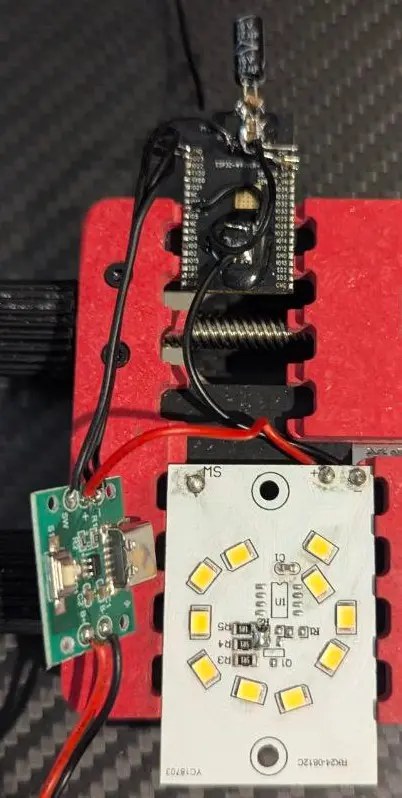
Step 2: Modifying the original LED controller board
The original controller board has the controller IC in the middle of a ring of LED’s.
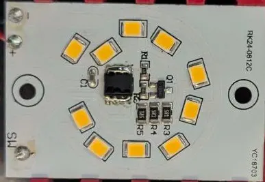
As we are going to replace the function of the original control IC in the middle, I removed it and shorted the +ve connection directly to the LED resistors.
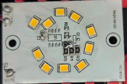
Shorting the pad to the resistors directly connects the V+ line to these LED’s, this way we can low side switch with the mosfet.
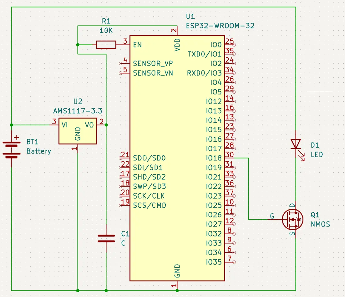
Step 3: Wiring up the ESP32
As I have a bunch of ESP32-Wrover modules from old projects I dead-bugged another one for this project. If you are doing this yourself you will just want to use a development board. As the battery voltage is > 3.3V we use the linear regulator to power the ESP32. If you have a dev board you can use the usb 5vin for power to use the onboard regulator (but do not connect USB and the battery at the same time).
Step 4: Loading ESPHome
If your dev board has a USB connection, you can use it with the ESPHome flashing as per normal. As I’m using a bare module, I used a “ESP32 Auto Downloader” module. These are great as they are a USB to UART converter + the circuit to toggle reset and GPIO0 boot pins for you. This is an example one, but there are many
Once the ESPHome firmware is loaded, all future updates are installed over WiFi so the connection is only required once.
ESPHome configuration
The ESPHome configuration is super tiny and boring as its just a single LED channel. Add this block to the bottom of the automatically generated template to add the LED output.
output:
  - platform: ledc
    pin: GPIO18
    id: ledc_lamp

# Example usage in a light
light:
  - platform: monochromatic
    output: ledc_lamp
    name: "Mushroom Light"
Final Result
The insides of the lamp look like this wired up:
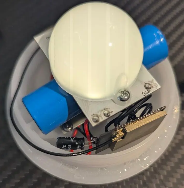
The ESP32 board is tucked into the side of the existing holder and fits well. By retaining the charger board from the bottom of the unit; USB charging still works and the USB-C power is kept.