This wasn’t going to become a blog post originally.
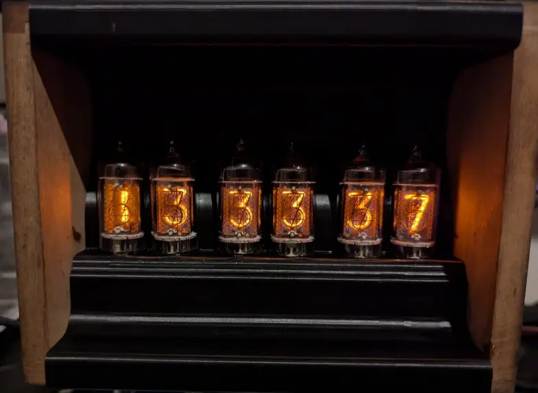
Gamiee sent me some very nice nixie tubes recently, and as one does, I wanted a desk clock using them. Seeking the warm fuzzy feelings only the orange glow could give.
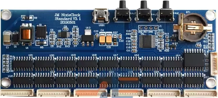
Original Control Board
Originally the plan was to use the cheap Aliexpress driver boards, and I picked up this one in a sale for sub $30AUD.
 These are fairly easy to wire up, however after writing it up it became obvious that this unit had features and settings but I couldn’t track down good documentation on how to enable them. Asking the seller didn’t result in anything either.
While the clock looked great in the wood+3D printed case, it could only set time. I was hoping this board would support features like turning off the display automatically at night but I didn’t find an easy way to set this up.
The clock design came about as I wanted to have a black or darker colour behind the tubes to make them pop out more. The wood case was upcycled from an old multimeter resistance divider unit, and a black 3D printed frame holds the tubes in place.
Micro-controller surgery to ESPHome
The controller board itself was very neat, with a nice HV generator and all of the shift registers and open drain drivers to run the tube elements.
After squinting at the board, the STM 8S 8-bit micro-controller is fairly easy to ID. Given that the basic topology is fairly obviously 74HC595 -> ULN2003 -> Tube for controlling the segments.
Quick testing with a multimeter confirmed that the 74HC595 shift registers are all in a chain, 8 chips total for 64 outputs. Sadly the OE pin was hardwired so no trivial software dimming for this board.

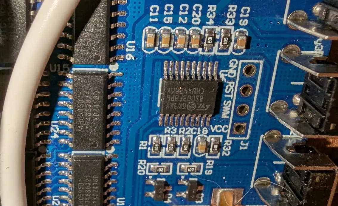
Quick multimeter probing identified the base pinout of the micro-controller. Showing all the expected signals for the 595 as well as the onboard I2C clock chip and the three buttons.
At this point I had already attached the board into the enclosure, so careful soldering was done via a longer soldering iron tip to reach down into the enclosure.
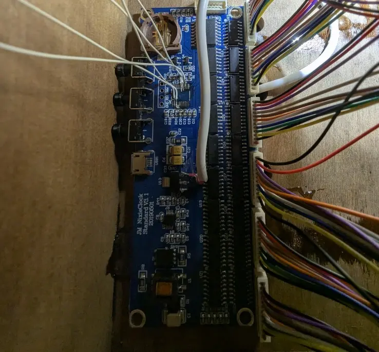
After attaching the break out wires from the board, I dead-bugged the ESP32 module with some input filter caps and loaded a blank ESPHome image to it. After wiring this in it was time to get some basic ESPHome happening to setup the clock to be functional again.
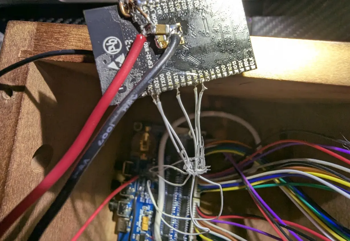 And yes, that is a completely dead-bugged WROVER unit, and it works completely fine.
Annoyingly, there is no nice way in ESPHome to write to the 595’s without defining all 60 output pins (which is not going to happen).
So I made up a hacky and small external component based on the 595 driver code to take in a 6 byte array and decode this to show on the 6 tubes.
The code for this is located here, along with an example ESPHome config file. I’m not saying this is great code, but it “works for me”, and should help if you want to make a similar project.
Anyway, may the code help someone else or inspire future developments.