I picked up a Mac Pro 2008 2.8GHz model locally, and it worked well when I first powered it up and loaded snow leopard on it.
However, I then upgraded the GPU in it (for fun) and the PSU went bang (loudly). As new PSU’s are hard to come by / expensive locally (and I couldn’t find an easy issue to fix upon opening) the Mac has been upgraded to instead recieving a refit of new insides.
I had been intended to make a “for lols” machine with the old Xeon CPU’s with a modern 2080Ti to run ollama on for home assistant. So now it will just get a vaugely newer CPU setup.
Below are all of my notes on the process of modifying the mac to fit a standard mATX motherboard setup. In the end it actually works exceptionally well; the perforated front grill works fantastic for ventilation and the dual-chamber design allows exiling the PSU into its own well ventalated cavity (like Apple did, we can still use it).
The final build is specced out as:
- Processor: Intel i3-10100 (former NAS leftover)
- Motherboard: Some low cost ASUS Prime (former NAS leftover)
- RAM: 16 GiB DDR4-2400 (On loan from work until prices are sane again)
- Boot drive: 500GiB Samsung 850 EVO (Left over, old main pc boot drive from back when these were new)
- Bulk storage: 2x 3TiB WD in mirror
- HBA: Some random LSI card i had on hand
- PSU: Thermaltake PSU from 2019
- GPU: Nvidia 2080
During the build photos you will see other parts come and go, often I use older or known parts during testing to reduce risk
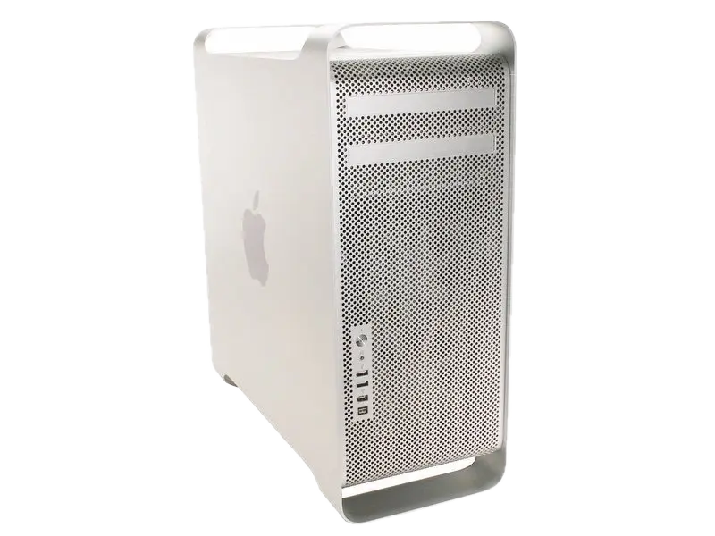
Credit for top image: from iFixit — Replacing/Upgrading Mac Pro Processors (Early 2008)
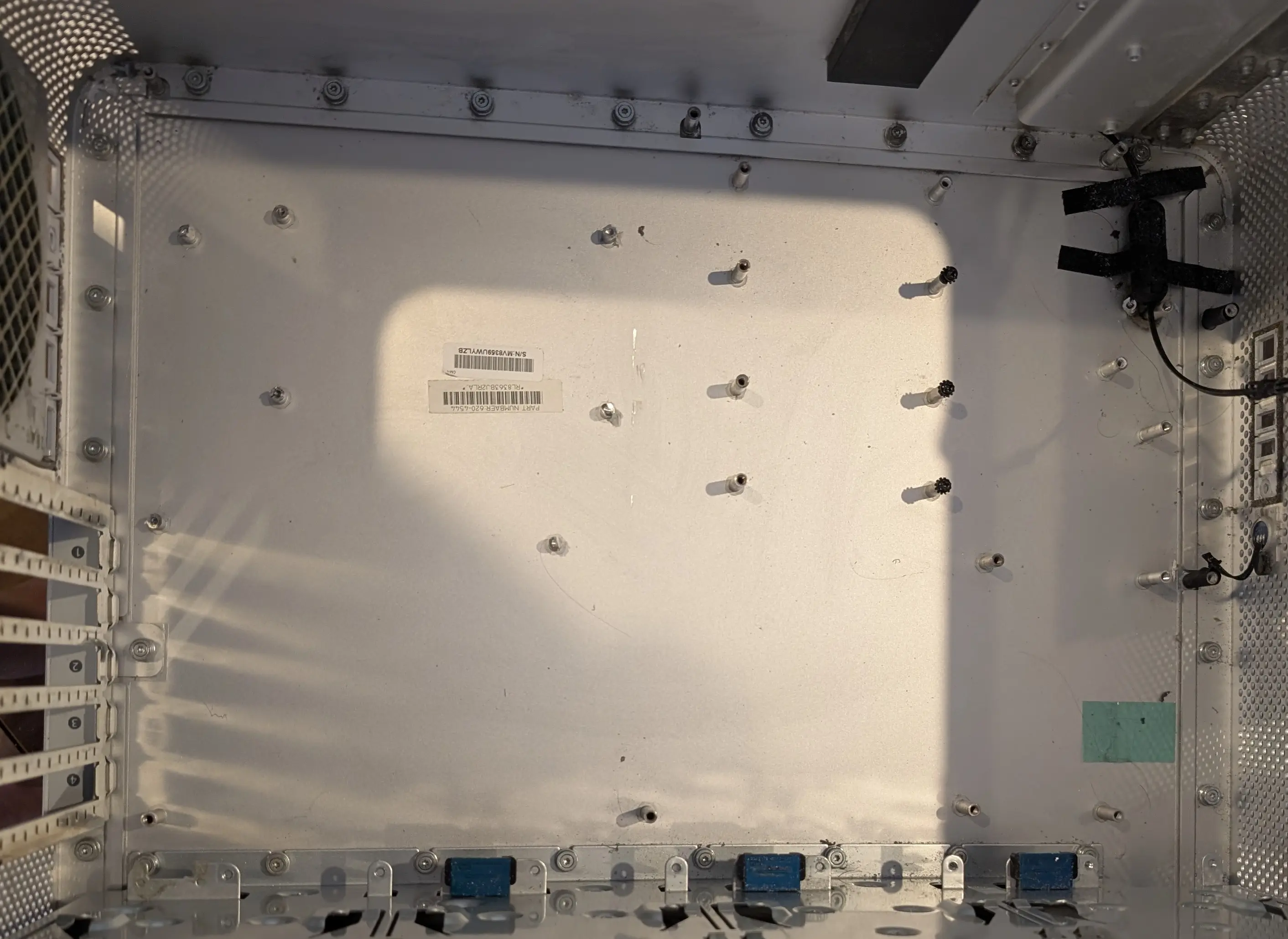
Emptying the chassis
Using the iFixit guide tear down the mac pro until you have everything removed. Go past the end of the guide and remove the main board, HDD sleds etc. It took some faffing with mine to get the PSU (which is what failed) out of the chassis, remember to take out the cover at the back of the DVD area and undo the velco first.
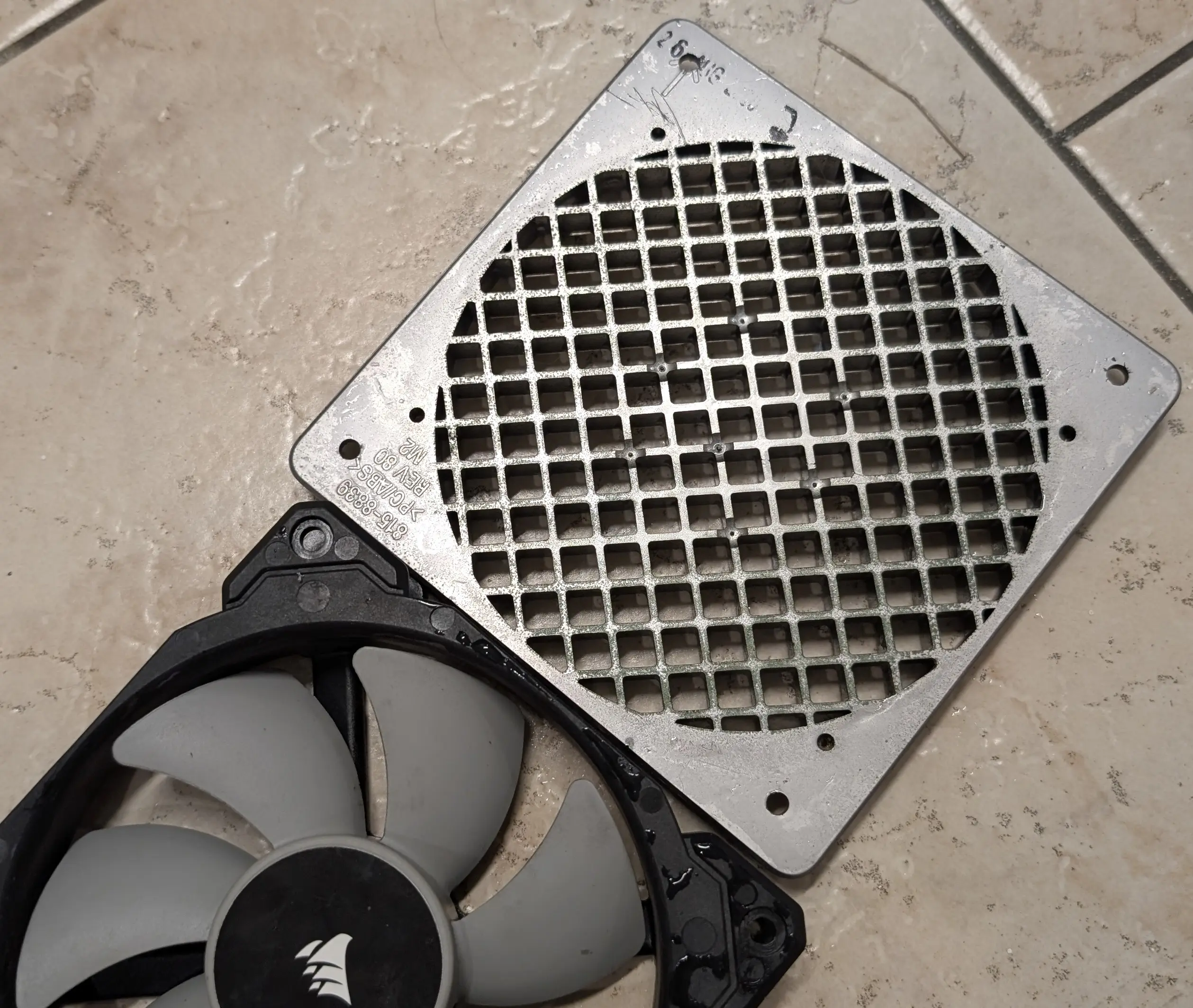
A note on fans
It’s tempting to connect the apple fans directly to the new motherboard as they use the same connector. However apple did not use the normal PWM control that we are used to. So these fans will run not run at all unles you pull their control wire to +12V. Some people have found tying this to 12V pin and using motherboard DC control to work. The speed control pin on apple fans of this era is analog voltage control 0-12V. You can use a transister + rc filter + pullup to build this from the 12V signal as well, but again, more faff.
I instead just replaced fans with other ones I had on hand to save time. They are all 120mm, so new fans are relatively easy to come by, and skips any messing around.
Planning fitment
Once the teardown is done, the case was empty enough to start planning.
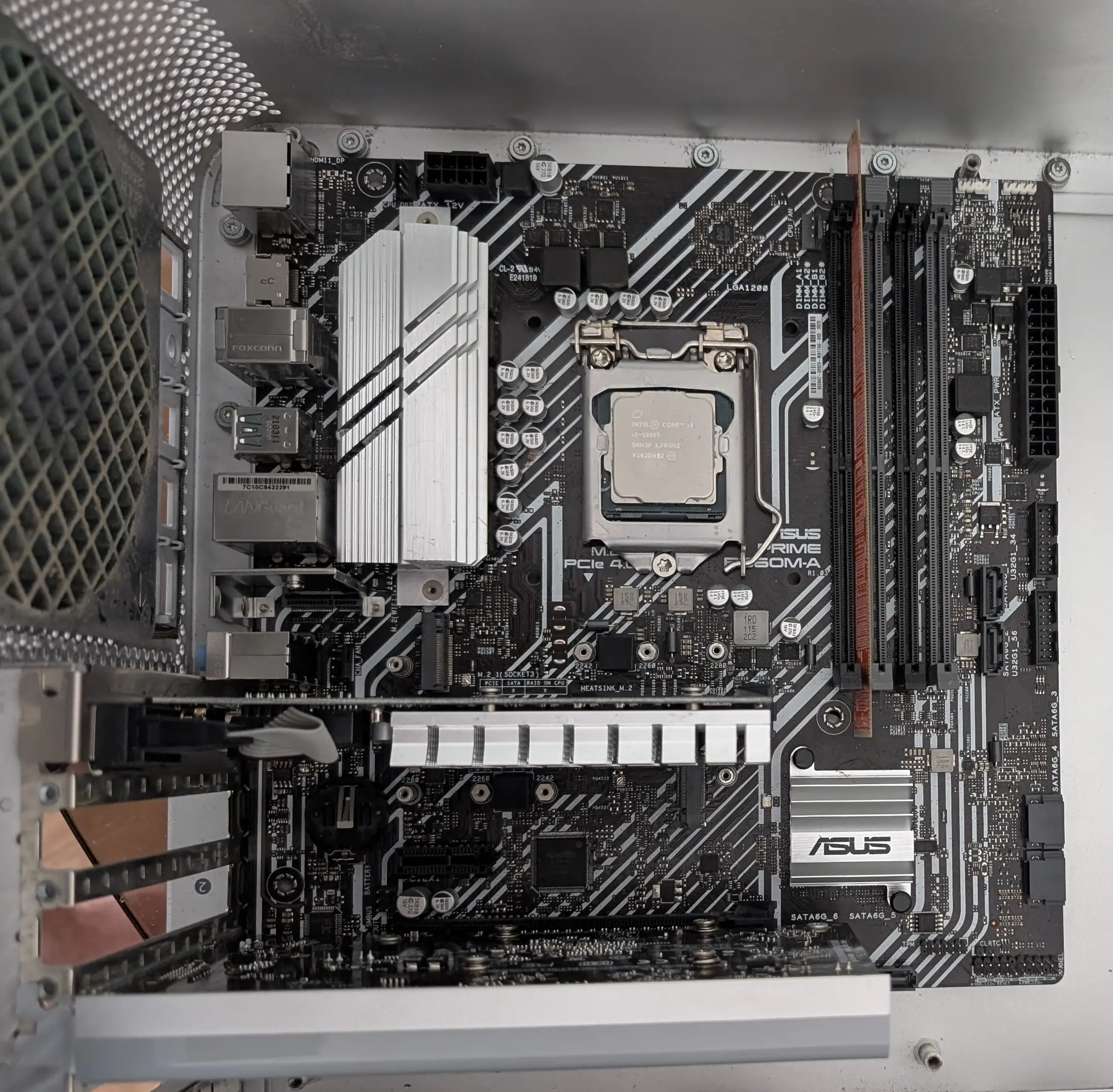
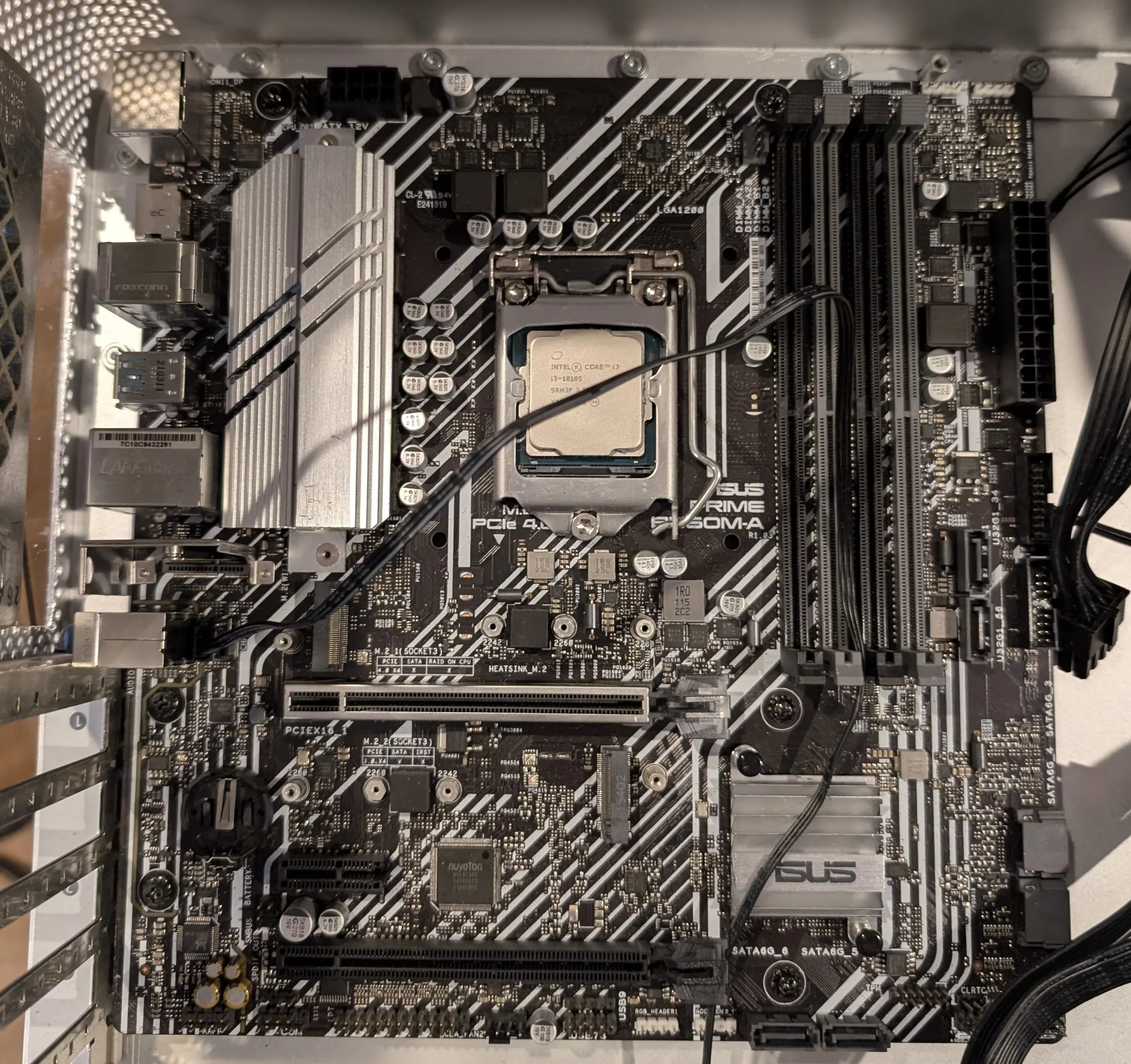
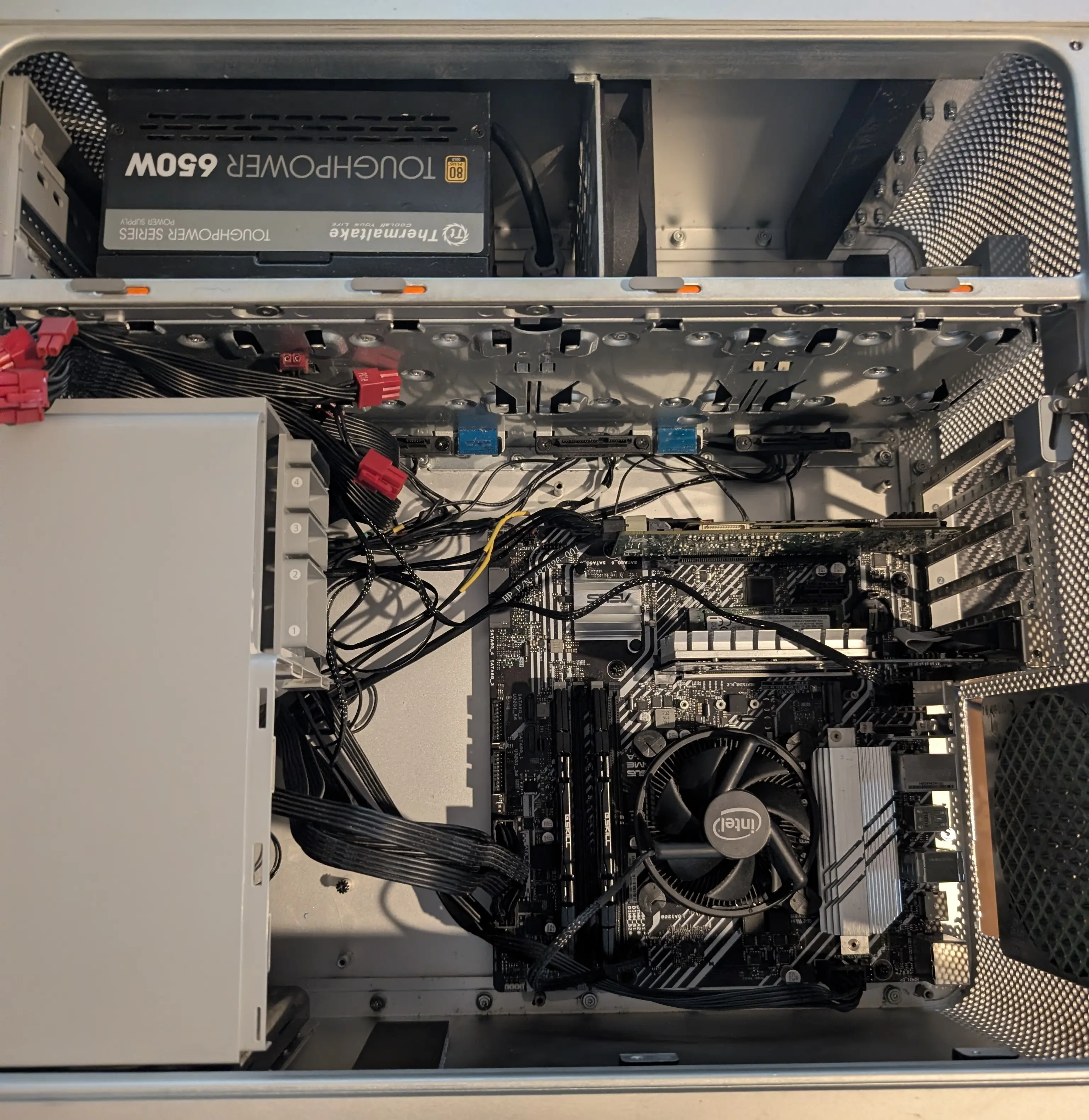
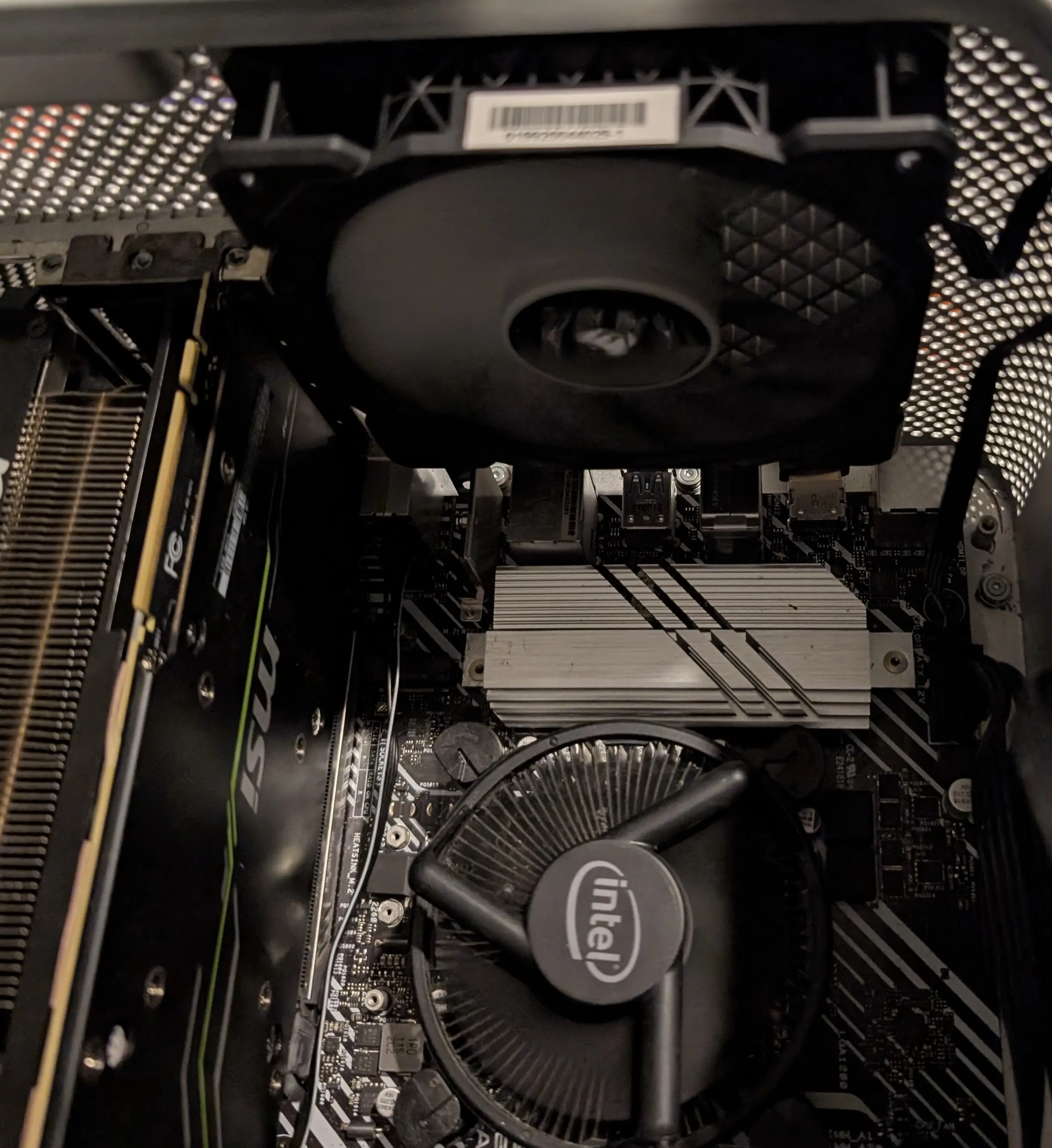
I already had an mATX motherboard in stock, this used to be the main board in my NAS for a few years. For now my plan is to set up this new PC build for compute and experiments rather than desktop use. I prefer mATX over ITX for any build I do as I always end up needing two PCIe slots for something. So all my builds around here tend to be mATX or full ATX. The chassis of the Mac Pro can’t fit a full size ATX, so keep in mind if you (for some odd reason) decide to do this, that you will need mATX or smaller.
The motherboard fits well in the case, with clearance on all sides. Except that the audio jacks end up jammed up against the case. I do not neeeeeed audio for this use case so I dont care that they will be near impossible to get to. Though if you are doing this and need them, you will need a wider cutout at the end.
It’s important to use more than one PCIe card for holding the board in alignment, as one card will allow twisting when testing alignment. Even with the two cards I’m using for testing (an old nvidia 210 and the macpro 120) there is a fair about of wiggle room in the exact alignment.
Mounting Motherboard
The existing mounting standoffs in the mac do not align with any of the mATX mounts sadly. But we can still semi re-use them. After a lot of faff (and bad design descisions) I ended up with this 3D printed frame, this has clerance for where the mac standoffs are to pass through it; and standoffs of its own to mount the motherboard to.
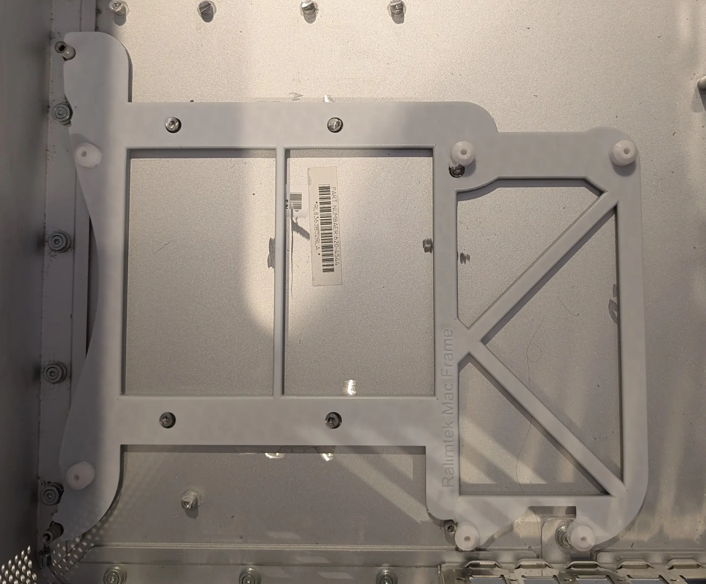
This means that it uses the existing mac mounting hardware to align to the case and lock into position in X/Y. Sadly however, the mac standoffs are too tall and will short out any motherboard you place on top of this frame, so using an angle grinder I cut these down so they are more like small stubbs. I did this rather than snapping them off as some people do as they form good anchor points to adhear the frame to.
The original mac standoffs are ~= the same height that the top of the frame needs to be at, so by cutting them down at least 3mm we ensure they dont touch the motherboard. The mounting stanoffs outside of the motherboard area are left intact since I can probably re-use them for something in the future (or at the least, they are not in the way). You can see in the above image of the frame, the standoffs are cut down and the threaded part is removed. You could of course re-drill and re-thread these, but is easier to just use them for alignment. The frame is desined to be a slight interference fit between the mounts on the left and right side, so that it snaps into place.
With the frame in place pressing on the stanoffs, I used UV epoxy to adhear it to the case where the stanoffs were. I also deliberately marked up the case a little with the angle grinder to give some texture for the epoxy to grab onto.
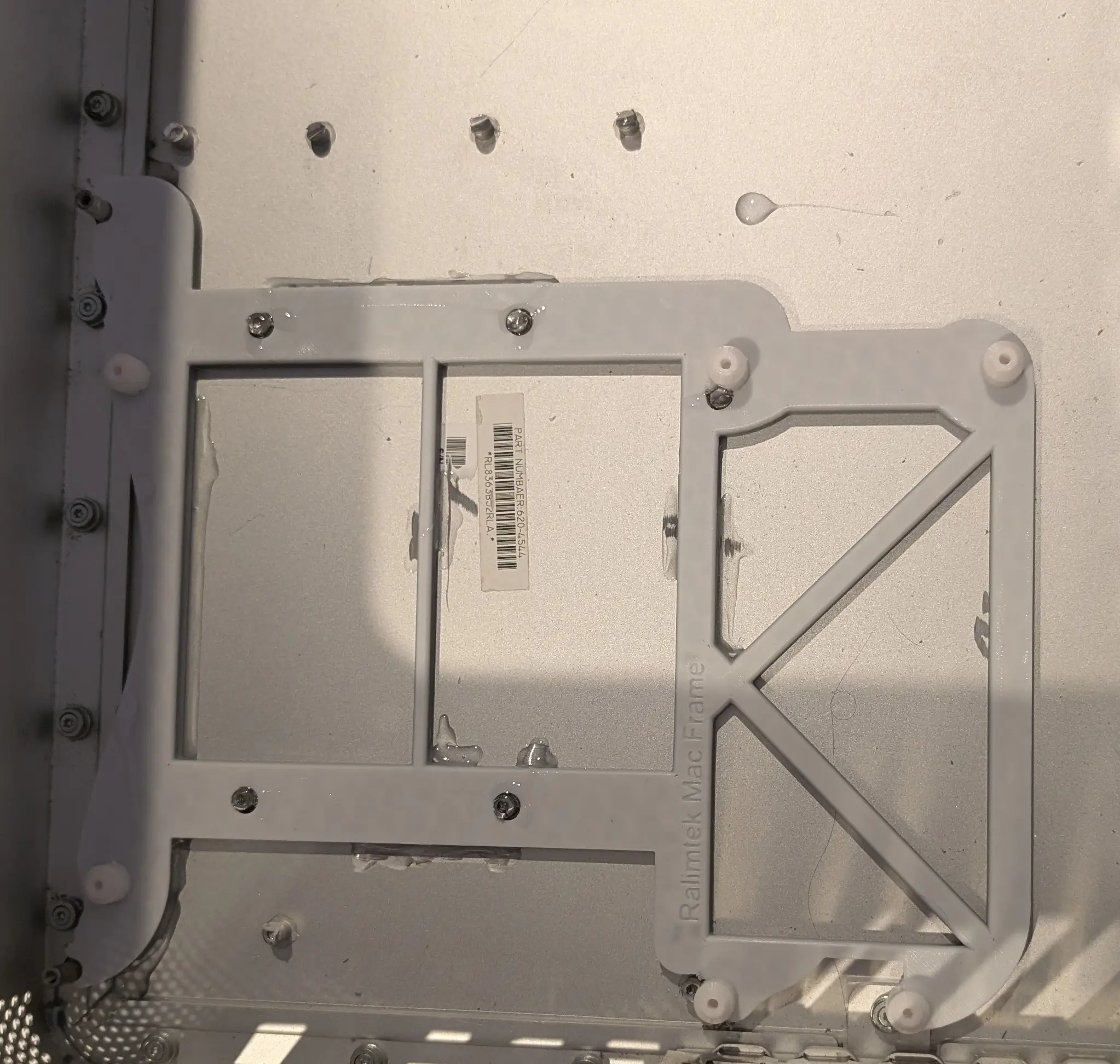
You can see some of the glue used, and the frame sticks in quite well. The glue isn’t the only thing holding it down at the end, as the PCIe cards also lockthe frame into place, and as the motherboard ends up upside down the PCIe cards are at the top of the case.
A design quirk I’ve come to like when making mounting frames like these, is to melt in screws rather than thread the plastic. I’ve struggled to get small threads to print in place or have them hold a tapped hole. So what I do instead is heat up the screw with soldering iron and gently push it down to melt it in. Similar to how you melt in a threaded inserts. This tends to melt in the matching threads fairly well, so the screw can be removed and re-inserted.
Once the motherboard is lined up (line it up by mounting PCIe cards to align those with the slots); I used this trick to melt the scews into place to hold the motherboard in.
As the screws used do not matter using this method, I re-used the black ones from the mac for this installation. When melting in screws I try to bias them alternatively at opposite sides of the holes, since you can’t torque them down to bite into the board.
Power supply
As I’m not going to need CD/DVD disk drives (thankfully), I have decided to mount the PSU in the disk area, as ths means that the power supply cables easily reach through the existing passthrough hole.
To re-use the existing disk drive mounting area for the PSU, I 3d printed small clips to re-use the screws.
 These are adheared to the PSU with doubled sided tape. This allows it to still be removable.
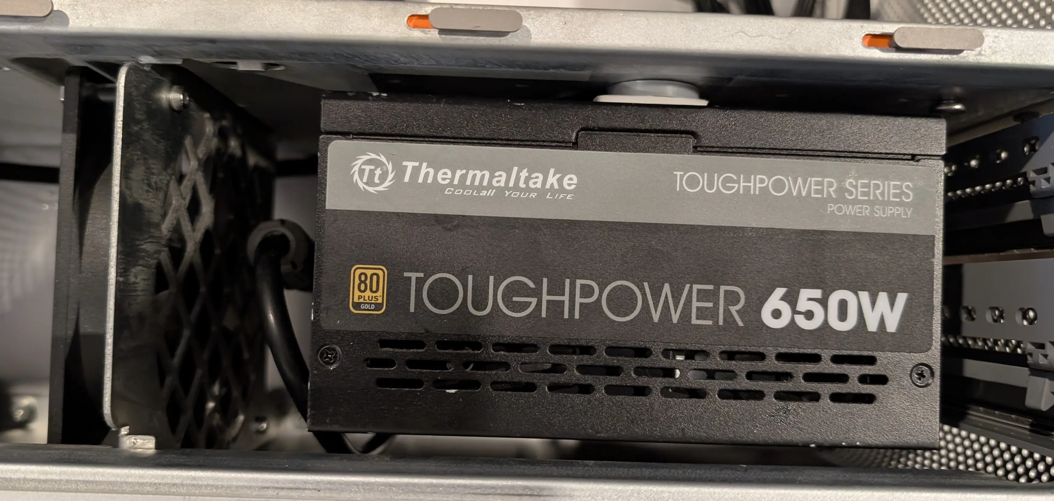
The PSU is then mounted into the case using these clips to hold it in place where the disk bay was. Once the case is closed, the lid stops the PSU backing off the clips
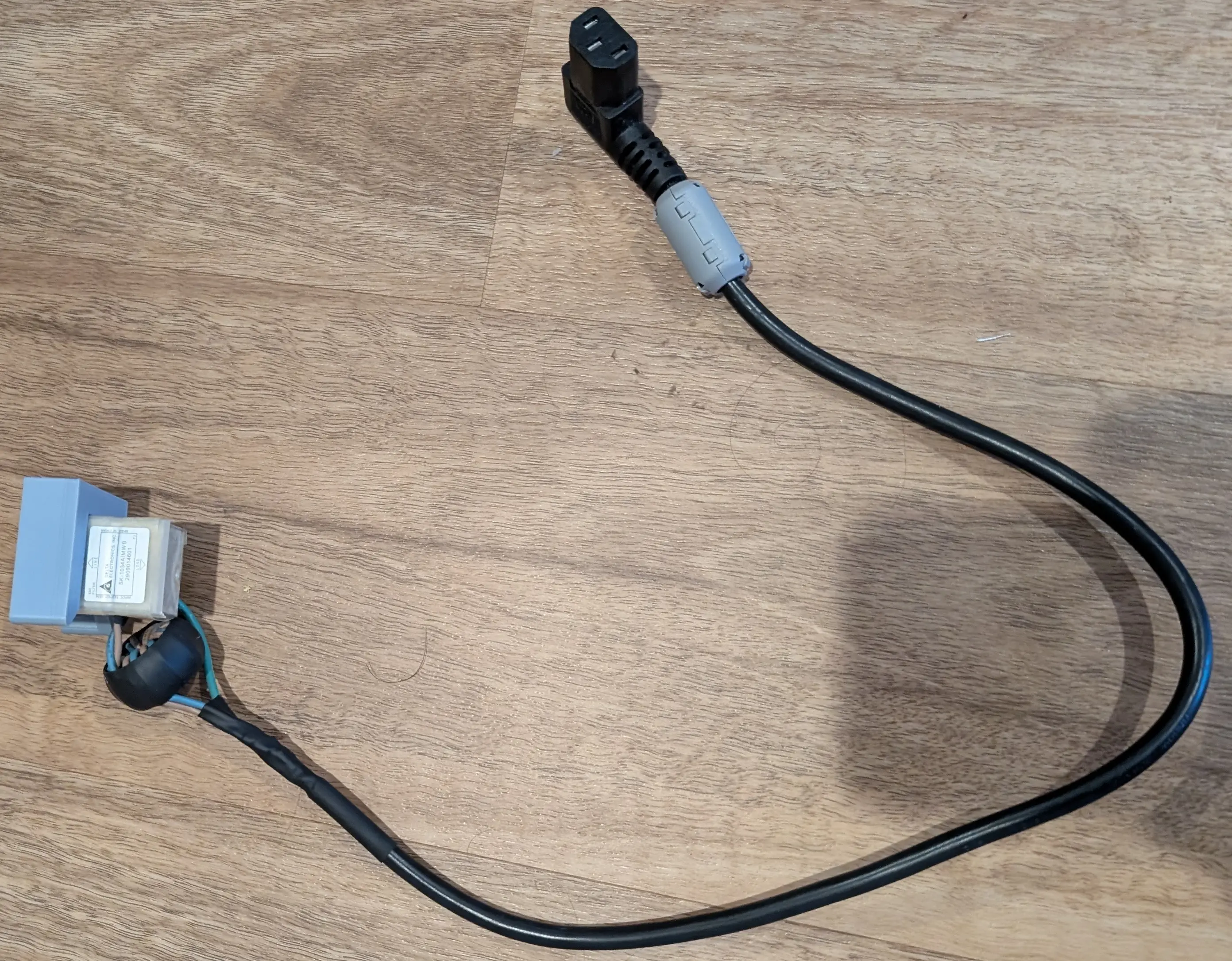
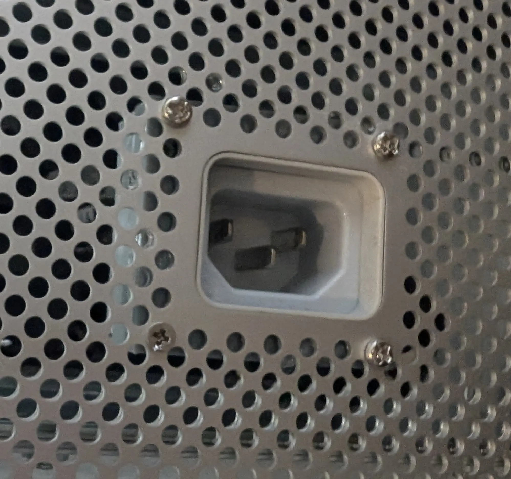
I made up a custom IEC extension cable using a right angle connector to join to the original power input port (removed from the dead PSU).
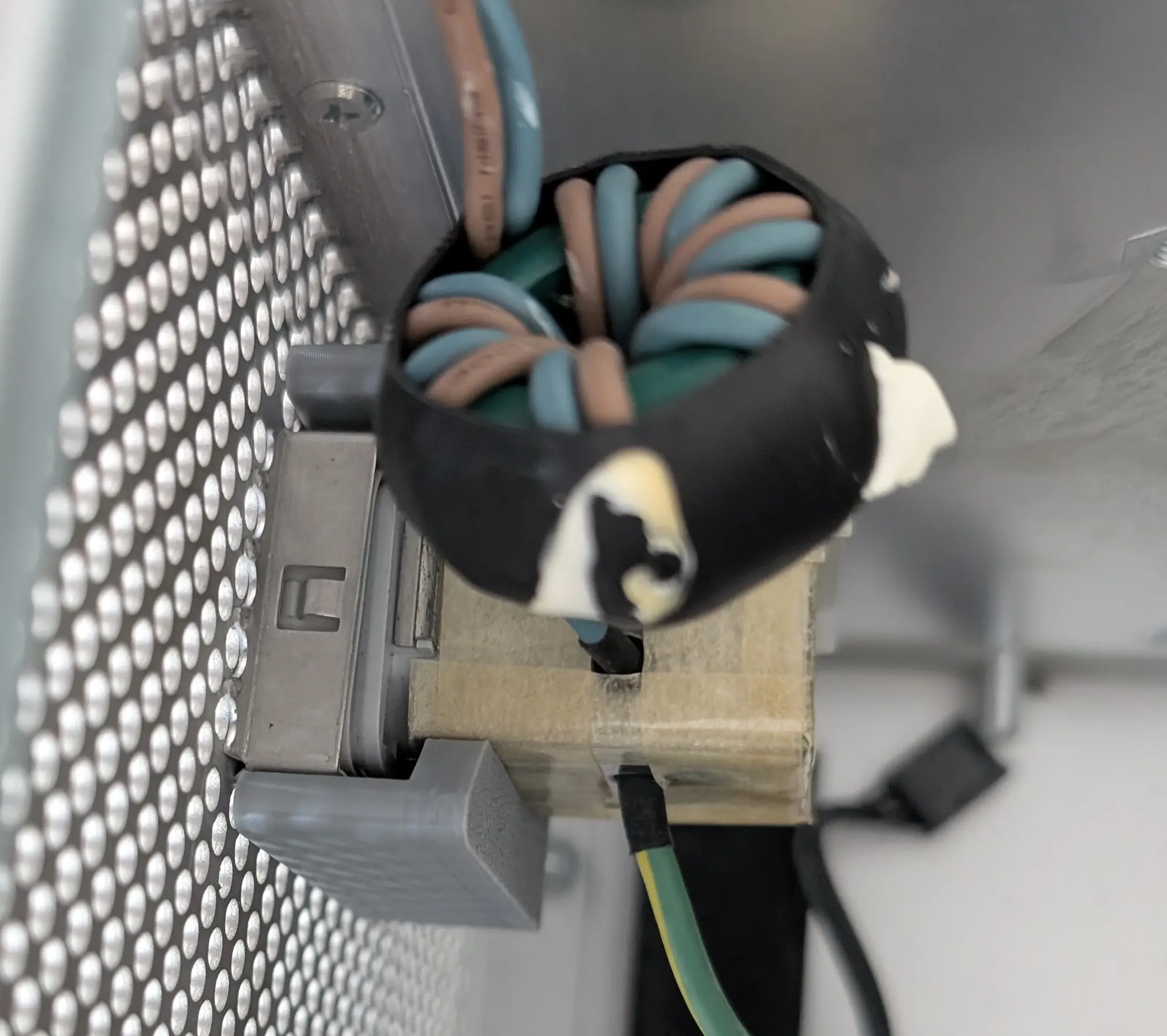
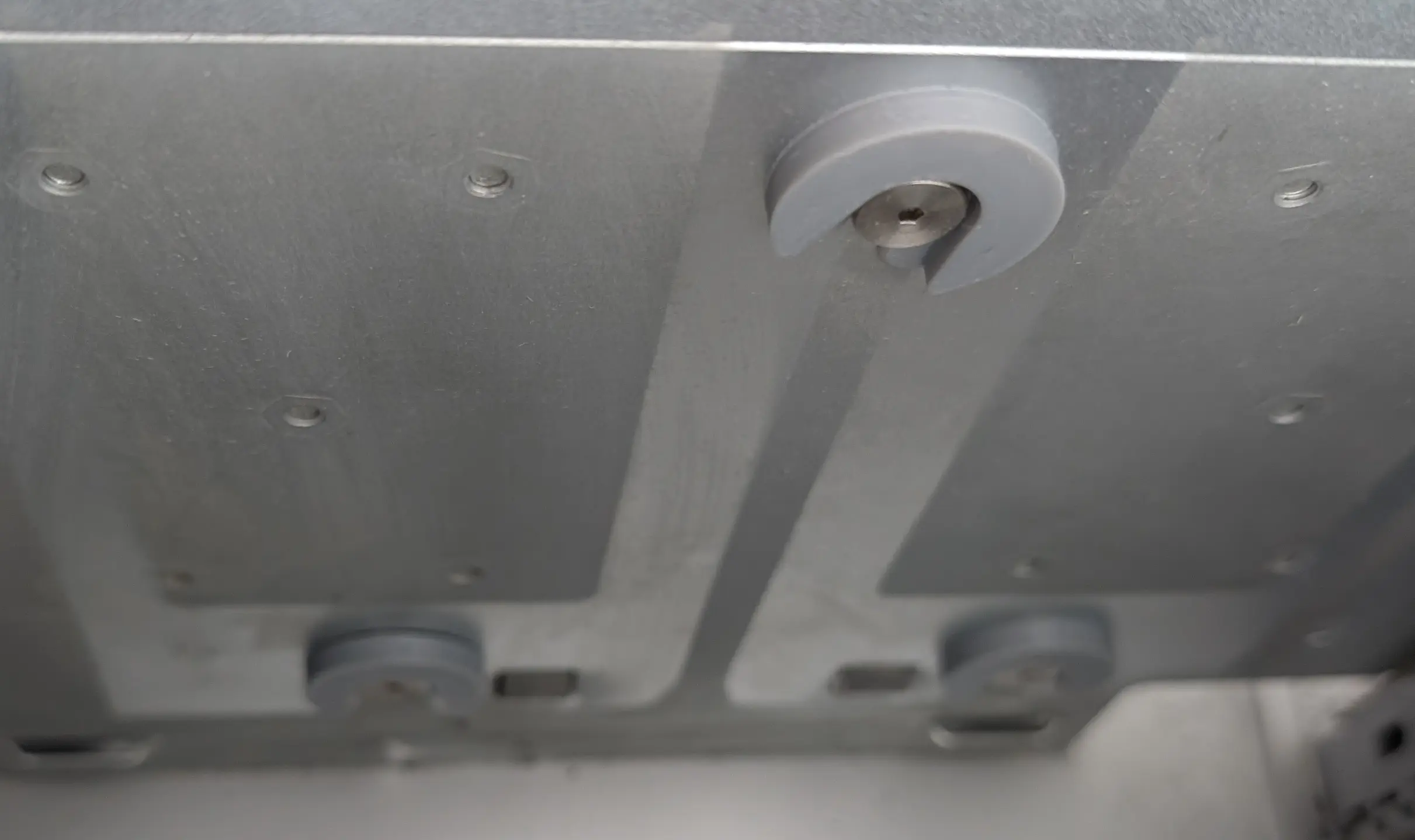
 The old power inlet port is held in place using a 3D printed clip that is then mounted to the case using screws from the back. I used the same method of just melting screws through to hold it in place. I will probably eventually replace these with matching ones… Maybe.
The cables from the PSU are fed down the hole that was originally used by the old power supply setup.
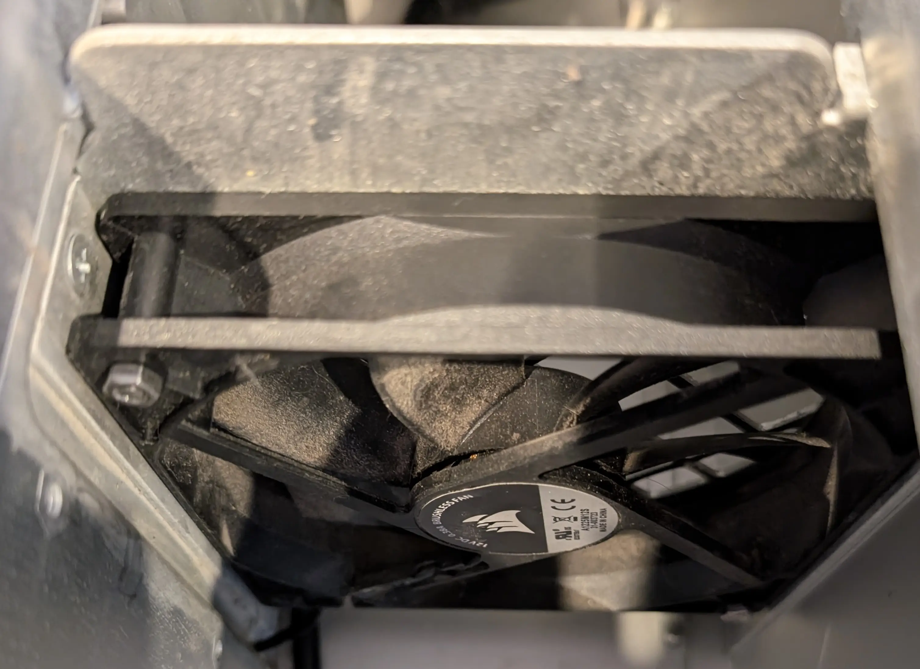 An old 120mm fan was mounted in the place of the Apple one that was originally in this top section. In BIOS it was locked to its lowest speed to just provide ventilation of the PSU out the back of the case.
Due to the tight space I did not find it easy to get fan screws in the fan, so instead I used M4 bolts and nuts to mount it in place. Remember to use a thread locker on these; as they will come undone otherwise.
An old 120mm fan was mounted in the place of the Apple one that was originally in this top section. In BIOS it was locked to its lowest speed to just provide ventilation of the PSU out the back of the case.
Due to the tight space I did not find it easy to get fan screws in the fan, so instead I used M4 bolts and nuts to mount it in place. Remember to use a thread locker on these; as they will come undone otherwise.
When installing the fan its a very tight fit, the spot where the fan finally mounts to is actually slightly recessed to give clearence. I found it required a bit of force to snap the fan into place.
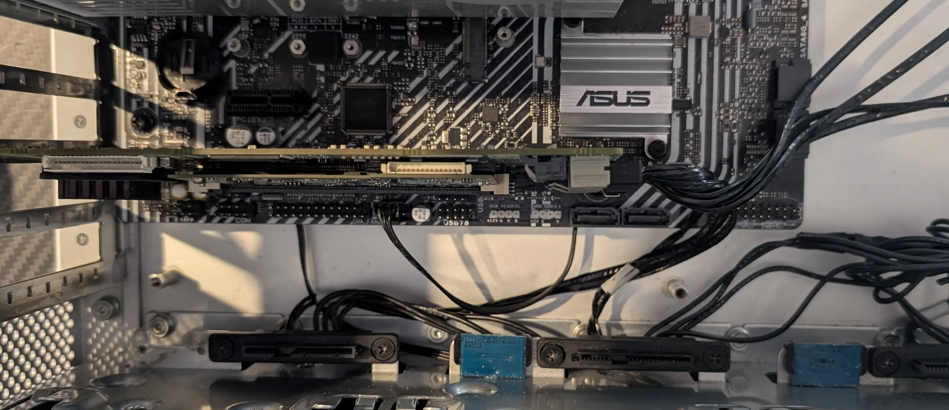
Hard Drive bays
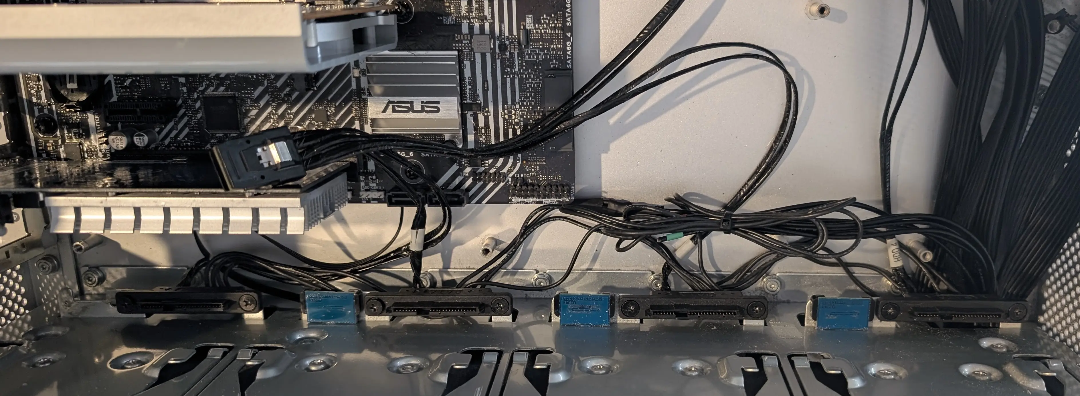 The existing hard drive bays can be used; along with the existing wiring harness. The harness connects 12V/GND/5V from the drives out to a 6 pin connector. Using a multimeter you can faiirly easily probe the sata power connector to find the cable pinout.
Once the existing power connection is adapted to suit your PSU connections, the existing SAS SFF-8088 plug can be plugged into a HBA card and used as is.
The existing hard drive bays can be used; along with the existing wiring harness. The harness connects 12V/GND/5V from the drives out to a 6 pin connector. Using a multimeter you can faiirly easily probe the sata power connector to find the cable pinout.
Once the existing power connection is adapted to suit your PSU connections, the existing SAS SFF-8088 plug can be plugged into a HBA card and used as is.
To make the harness reach the drive bays, un-mount the SATA connectors, and then flip the long pair around so that they are on the other side of the connector. This places the SFF plug in the middle of the four bays and almost perfectly lines it up to connect to a card
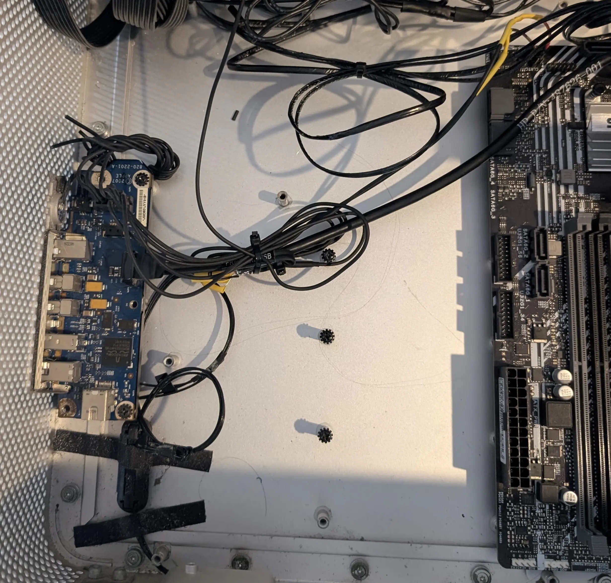
Front panel
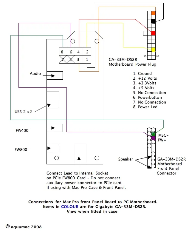
Smart people have long ago figured out the pinout of wiring the front panel up to be used with an ATX motherboard.
I will note that you may need to try both of the power switch pins / power led pins to figure out which one works well with your motherboard. Both are active low. So it pulls the power signal to GND when the button is pressed, and when the led input is GND’ed then the led turns on.
I wired up 12V/3.3V to the breakout cable from the PSU. 5V was wired to the USB header along with the USB lines on the SATA connector.
The power button and front led appear to work if either 5V or 3.3V are available. I set USB to always be powered in the motherboard settings.
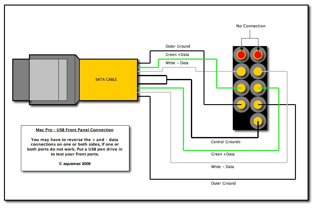
Apple used a SATA cable to connect the USB 2.0 ports to the main board. I cut the end off the cable and joined it to a USB 2.0 motherboard cable. The above pinout was used as a reference, but I did find for my board I had to flip the USB data pairs
Front fan mount
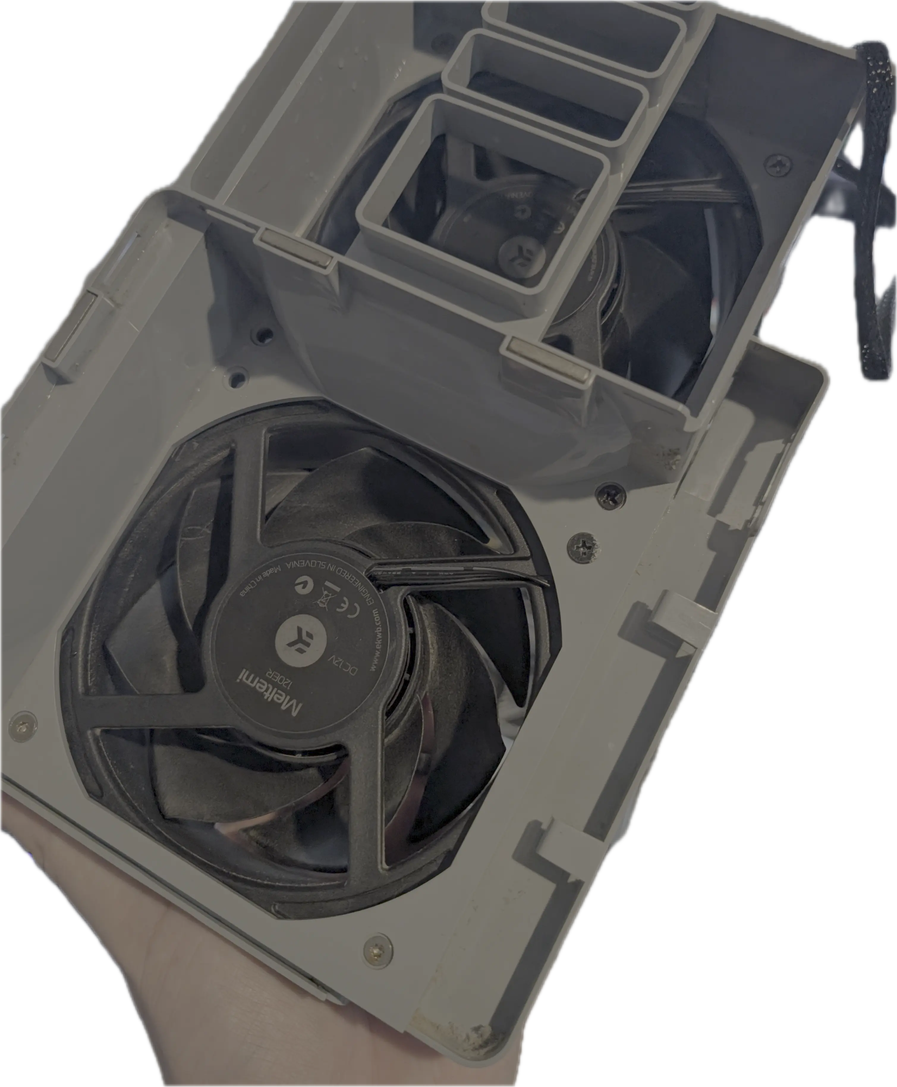 This is a simple mod, the old Apple fans can be removed and they are standard 120MM fans, I installed two new fans using screws to mount them.
 After re-installing the black plastic mount at the bottom of the case, these can be re-installed and even the screw that used to go through the motherboard can be re-installed to lock in place.
In the original mac, there is a metal cover that clips to the fan shroud that guides the bottom fan to go directly over the CPU. You can re-install this guide to again direct the bottom fan to serve as RAM+CPU cooling.
Back of case fan
The back of case fan grill in the apple case is sized perfectly for a 120mm fan.
There are four small phillips #1 screws hidden around this ring in the back of that case that hold the plastic grill in.
 Removing these allows it to be easily removed. Lining up the fan and just drilling out the mounting holes works well, then normal fan screws can be used to mount the fan.
Once the fan is mounted to the plastic grill, the original four screws can be used to mount it back to the case.
Cutting out the back case
The main downside to reusing a mac pro case is that the original mac back panel IO is offset back further than the PCI slots. Where as on an ATX motherboard they are all in-line to keep the outline of the board rectangular.
This results in the ports being recessed in on the case, so that cable connectors are a little harder to connect.
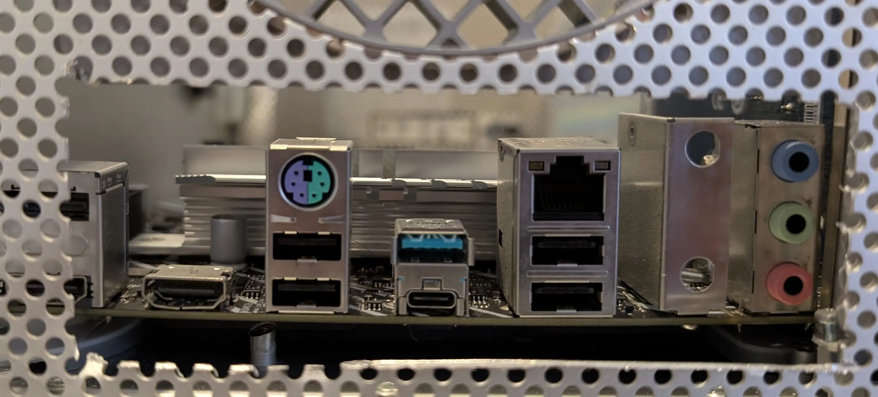 To expose the motherboard IO you need to cut out the old Apple IO plate area.
I only cut out the old panel area and didnt fully expand the cut-out as I only need access to Ethernet+USB+HDMI.
To expose the motherboard IO you need to cut out the old Apple IO plate area.
I only cut out the old panel area and didnt fully expand the cut-out as I only need access to Ethernet+USB+HDMI.
Future work
Each of the hard drive mounting bays has a small temperature monitoring module. This has an LM75 I2C temperature sensor on it. Each one is configured to a different I2C address by the wiring harness. If you wanted to have temperature monitoring of each HDD external temperature, you could wire this up to an I2C header on your motherboard (or one in an unused video port), or an external USB to I2C adaptor.
As I’m happy using smart data I have not connected these, but it would be relatively low effort to connect them if one found a good usecase for this.
Performance & Final build
After the whole unit is assembled, it works very well, the case has great airflow due to the design and dual front intake fans keeping the case positively pressured.
It keeps almost the entire design stock, so the aesthetics stay the same. The machine has now been running perfectly for my use cases; and it looks good tucked in the corner.